Arduino Code for Controlling Motors
Arduino Code for Controlling Motors ,The AFMotor library, which interfaces with the motor hardware, anticipates a PWM value ranging from 0 to 255. Therefore, the motorSetSpeed function in the RobotMotor library utilizes the map function to convert the percent into a PWM value, as demonstrated in Example 7-1.
Example 71.
Setting the motor speed; from RobotMotor.cpp
void motorSetSpeed(int motor, int speed)
{
motorSpeed[motor] = speed; // save the value
int pwm = map(speed, 0,100, 0,255); // scale to PWM range
motors[motor].setSpeed(pwm) ;
}
The ‘map’ function is a versatile tool extensively utilized throughout this book. This function rescales a value from one range to another. For instance, the following code scales a value from ‘analogRead’ (ranging from 0 to 1023) to a percentage (ranging from 0 to 100):
int toPercent = map(val, 0, 1023, 0, 100);Keep in mind that the speed percentage controls motor power, which isn’t typically directly proportional to speed, especially at low power levels.
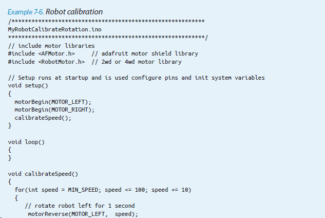
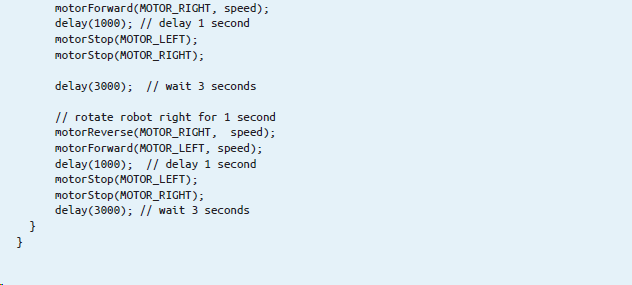
The power needed to initiate robot movement varies based on factors such as the motor, gearbox, battery voltage, robot weight, and surface conditions. While the process for calibrating the robot will be outlined shortly, let’s first delve into how the software manages robot speed control.
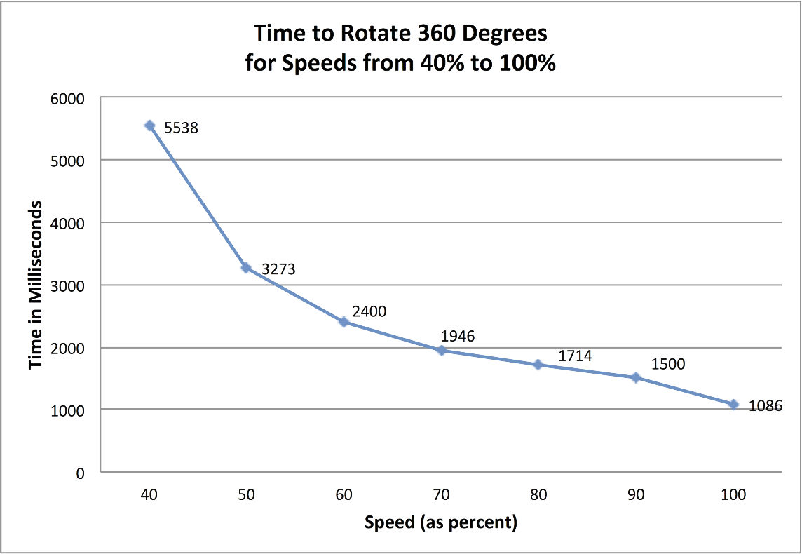
The code excerpt presented in Example 7-2 includes constants utilized for computing the necessary delays required to rotate the robot at various speeds. The variable ‘rotationTime’ holds the time duration for a complete 360-degree rotation across all practical speed settings. Speeds below the ‘MIN_SPEED’ threshold (40%) lack the requisite power to overcome friction within the drive system.
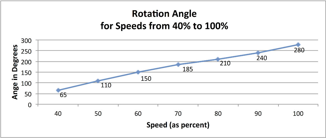
The relationship between rotation angle and speed percentage isn’t linear, requiring interpolation to calculate the duration for a full rotation at any speed (provided it’s as fast or faster than the minimum speed). Example 7-3 illustrates the code that utilizes the time table based on the data depicted in Figure 7-9.
The RobotMotor library contains the code to determine the time required for the robot to complete a 360-degree rotation. This duration varies between two-wheeled and four-wheeled chassis and fluctuates with changes in motor speed. Example 7-3 showcases the values utilized in the RobotMotor.cpp code for the 2WD chassis.
Please note that there are fewer entries in the tables for the 4WD robot, as this chassis requires a higher speed to initiate movement effectively.
The table entries assume speed intervals of 10%, so the value for MIN_SPEED should be a multiple of 10. There must be one rotation time per speed, so if you increase MIN_SPEED by 10, for example, you will also need to remove the first element in both speedTable and rotationTime.
The code in RobotMotor.cpp that utilizes the data in the rotationTime table remains the same for both chassis (refer to Example 7-5).
Modifying a Library for Arduino motor control
You’ve started with a clear Arduino introduction, explaining the difference between modifying an Arduino sketch and modifying a library. You then proceed to provide step-by-step instructions for modifying the RobotMotor.h file to support the 4WD chassis. This approach is helpful for users who may be unfamiliar with the process. By including specific instructions for finding the sketchbook location and opening the library directory, you’re ensuring that users have all the information they need to successfully make the modification. Overall, these instructions are well-structured and informative.
1: Open the sketchbook folder using Finder (Mac) or Explorer (Windows).
2: Navigate to the libraries directory within the sketchbook folder, and then open the directory labeled “RobotMotor.
3: Right-click (or Control-click on Mac) the “RobotMotor.h” file, and select “Open with” to choose a plain text editor. On Windows, you can use Notepad, while on Mac, TextEdit is recommended. For Linux users, any preferred plain text editor can be used.
4: In the “RobotMotor.h” file, locate the line “#define CHASSIS_2WD” and modify it to “#define CHASSIS_4WD”. Save the changes to the file.
While you need to quit and restart the Arduino IDE after installing a new library, you don’t need to do so every time you make modifications to a library.
Example 7-5.
Applying the rotationTime table
// return the time in milliseconds to turn the given angle at the given speed
long rotationAngleToTime( int angle, int speed)
{
int fullRotationTime; // time to rotate 360 degrees at given speed
if(speed < MIN_SPEED)
return 0; // ignore speeds slower then the first table entry
angle = abs(angle);
if(speed >= 100)
fullRotationTime = rotationTime[NBR_SPEEDS-1]; // the last entry is 100%
else
{
int index = (speed – MIN_SPEED) / SPEED_TABLE_INTERVAL ; // index into speed
// and time tables
int t0 = rotationTime[index];
int t1 = rotationTime[index+1]; // time of the next higher speed
fullRotationTime = map(speed,
speedTable[index],
speedTable[index+1], t0, t1);
// Serial.print(“index= “); Serial.print(index);
// Serial.print(“, t0 = “); Serial.print(t0);
// Serial.print(“, t1 = “); Serial.print(t1);
}
// Serial.print(” full rotation time = “); Serial.println(fullRotationTime);
long result = map(angle, 0,360, 0, fullRotationTime);
return result;
}
This Arduino code calculates the index into the speedTable array that is closest to (but not greater than) the desired speed, storing it in the variable t0. The interpolated time will fall between this value and the next index (t1), with the rotation time calculated using the ratio of the rotationTime value between t0 and t1 in the same proportion as the desired speed in the speedTable. For a clearer understanding of this Arduino process, refer to Figure 7-10.
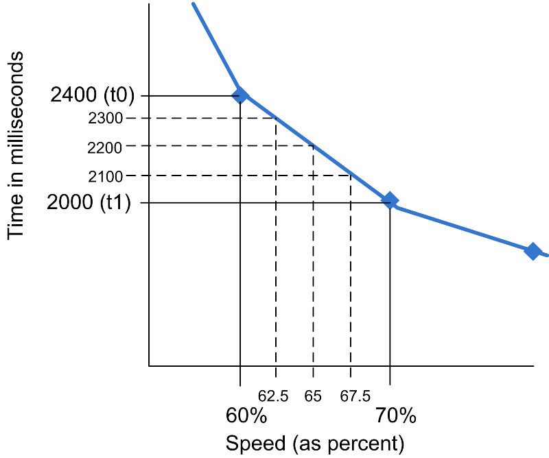 Figure 7-10: Speed Interpolation Diagram
For instance, at a speed of 65%, which lies midway between the values for 60% and 70%, the associated time will be 2200 milliseconds, equidistant from 2400 (the value for 60% speed) and 2000 (the value for 70% speed). Similarly, a speed of 62.5% represents 1/4 of the range between the table entries (60 and 70), resulting in a time that is 1/4 of the range between the corresponding speeds (2400 and 2000), which equals 2300 milliseconds. The map function is utilized to calculate this proportional value.
fullRotationTime = map(speed,speedTable[index],speedTable[index+1],t0,t1);
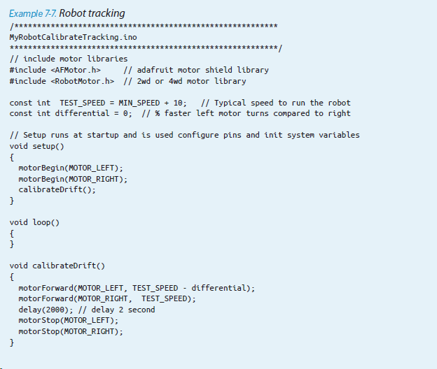
Adjusting Rotation and Tracking
Here is how the differential constant is used in the Arduino code:
&& speed > differential)
speed -= differential;