PLC S7-300 & Servo Motors Modbus Interface
Introduction:
In the realm of industrial automation, the integration of Programmable Logic Controllers (PLCs) with servo motors is essential for precise and dynamic motion control in various applications such as robotics, CNC machining, packaging machinery, and printing presses. By leveraging the Modbus communication protocol, PLCs can seamlessly communicate with and control servo motors, enabling operators to achieve unprecedented levels of precision, flexibility, and efficiency in their manufacturing and processing operations. This article provides a step-by-step guide on interfacing PLC S7-300 with servo motors using Modbus, covering the setup, configuration, and programming aspects of the integration.
1. Understanding Modbus Communication Protocol:
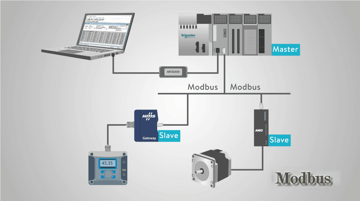
- Overview: Modbus is a widely used serial communication protocol in industrial automation for transmitting data between electronic devices. It operates on a master-slave architecture, where a master device (such as a PLC) initiates communication with one or more slave devices (such as servo motors).
- Variants: Modbus encompasses several variants, including Modbus RTU (Remote Terminal Unit) and Modbus TCP/IP (Transmission Control Protocol/Internet Protocol). Modbus RTU is typically used for serial communication over RS-232 or RS-485 interfaces, while Modbus TCP/IP is used for communication over Ethernet networks.
2. Hardware Setup:
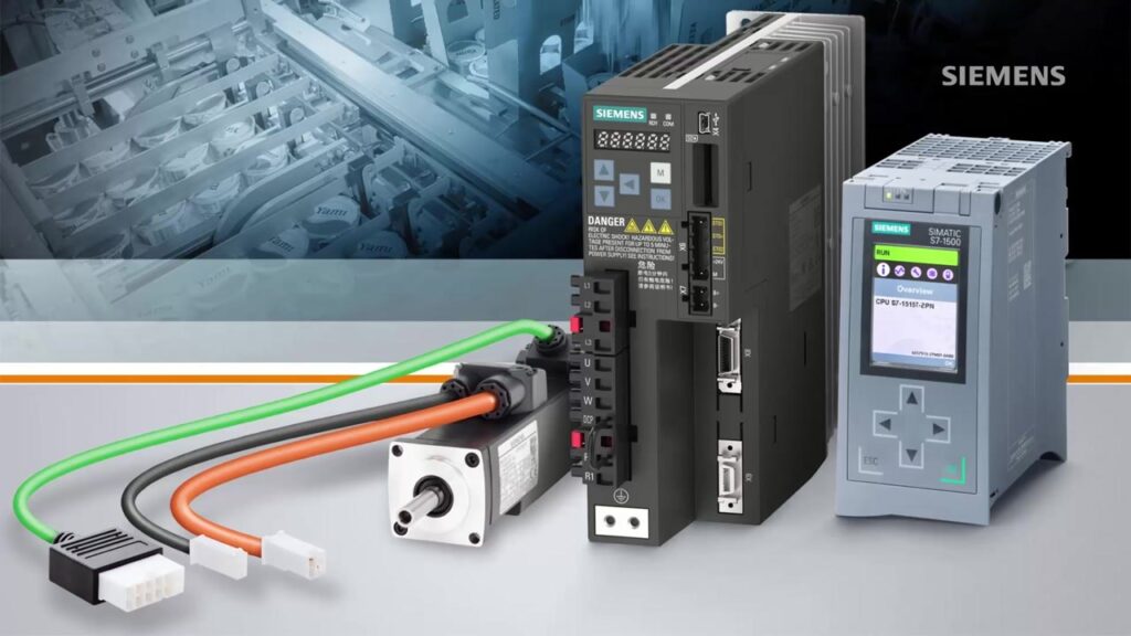
- PLC S7-300: Ensure that the PLC S7-300 is properly installed and powered on. You will need a CPU module with integrated communication interfaces or a communication module (e.g., CP341) to support Modbus communication.
- Servo Motor: Connect the servo motor to the PLC using a suitable communication interface (e.g., RS-485 or Ethernet). Ensure that the servo motor is powered on and configured for Modbus communication.
3. Configuration of PLC S7-300:
- Step 1: Configure Communication Interface: In the hardware configuration of the PLC programming software (e.g., Siemens STEP 7), configure the communication interface (e.g., CP341) for Modbus communication. Specify the communication parameters such as baud rate, data bits, parity, and stop bits.

- Step 2: Define Modbus Communication Settings: Define the Modbus communication settings in the PLC program, including the slave address of the servo motor, communication timeout, and error handling mechanisms. These settings will vary depending on the specific requirements of the servo motor and the Modbus protocol variant used.
4. Programming the PLC:
- Step 1: Open a Modbus Communication Channel: Use the programming software to open a Modbus communication channel between the PLC and the servo motor. This typically involves configuring communication function blocks or instructions that handle the transmission and reception of data packets according to the Modbus protocol.
- Step 2: Read and Write Data: Use read and write instructions in the PLC program to exchange data with the servo motor. For example, use read instructions to retrieve servo motor status and feedback data (e.g., position, velocity) and write instructions to send control commands (e.g., target position, velocity profile) to the servo motor.
- Step 3: Implement Error Handling: Implement error handling mechanisms in the PLC program to handle communication errors, timeouts, and exceptions gracefully. This may include retry mechanisms, fault detection, and error logging to ensure robust and reliable communication with the servo motor.
5. Testing and Debugging:
- Step 1: Verify Communication: Test the Modbus communication between the PLC and the servo motor by sending and receiving data packets. Use diagnostic tools provided by the programming software to monitor communication status, detect errors, and troubleshoot issues.
- Step 2: Validate Control Commands: Validate control commands sent from the PLC to the servo motor by observing the motor’s response. Verify that the servo motor moves according to the specified trajectory and follows the commanded motion profile accurately.
- Step 3: Fine-Tuning: Fine-tune the PLC program and servo motor parameters as needed to optimize motion control performance. Adjust parameters such as PID gains, acceleration/deceleration ramps, and position feedback resolution to achieve desired motion characteristics.
6. Best Practices:
- Documentation: Document the Modbus communication settings, PLC program logic, and servo motor configuration for future reference and troubleshooting. Maintain clear and comprehensive documentation to facilitate system maintenance and knowledge transfer.
- Modular Programming: Implement modular programming techniques to organize the PLC program into logical modules or functions. This improves code readability, reusability, and maintainability, especially in complex motion control systems with multiple axes and functionality.
- Version Control: Implement version control practices to track changes to the PLC program and servo motor configuration over time. Use version control software to manage revisions, collaborate with team members, and ensure consistency across different versions of the system.
Conclusion:
Interfacing PLC S7-300 with servo motors using Modbus opens up new possibilities for precise and dynamic motion control in industrial automation applications. By following the steps outlined in this guide and adhering to best practices, operators and engineers can seamlessly integrate PLCs and servo motors, unlocking unprecedented levels of performance, efficiency, and flexibility in their automation systems.
Resources and Further Reading:
For those seeking deeper insights into PLC Modbus integration with servo motors and its applications, a variety of resources are available. Manufacturers of PLCs, servo motors, and motion control systems offer comprehensive documentation, tutorials, and training materials on Modbus implementation, servo motor control, and motion control algorithms. Additionally, industry publications, forums, and online communities provide opportunities for knowledge sharing and collaboration among automation professionals.