Step-by-Step Guide to PID Control Using Siemens PLCs
In industrial automation, managing variables like temperature, pressure, and flow rate with precision is essential for optimal performance and product quality. PID (Proportional-Integral-Derivative) control is a widely-used control strategy that can help achieve these goals by dynamically adjusting control outputs to maintain setpoints. Siemens PLCs are ideal for implementing PID control, providing robust tools and libraries that simplify the process.
In this tutorial, we’ll dive into the essentials of PID control, how to set it up using Siemens PLCs, and some real-world applications that show its impact. This guide is perfect for those new to PID control who want to learn the steps for implementing it in industrial processes.
What is PID Control?
PID control is a feedback loop mechanism that regulates process variables by adjusting control outputs based on the difference between a setpoint (desired value) and the actual measured process variable. The PID controller works through three main components:
- Proportional (P): Determines the reaction to the current error, reacting directly to how far the actual value is from the setpoint.
- Integral (I): Accounts for past errors by integrating them over time, eliminating any persistent offset.
- Derivative (D): Predicts future errors by assessing the rate of change, helping to stabilize and smoothen the system.
By combining these three components, PID control can quickly and accurately bring process variables to their target values and maintain them.
Step 1: Understanding Siemens PLC Tools for PID Control
Siemens PLCs offer built-in PID control capabilities with user-friendly libraries and function blocks, especially in the TIA Portal environment. Here’s a look at the main tools you’ll need:
- PID Compact or PID Control Library: These preconfigured function blocks simplify the creation of control loops, minimizing the amount of coding required.
- TIA Portal: This Siemens programming environment provides the tools you need to configure, tune, and monitor PID control loops.
Understanding these resources will help you set up and adjust PID control effectively.
Step 2: Setting Up a PID Loop in TIA Portal
Once you’re familiar with the tools, you can begin setting up your first PID control loop in TIA Portal.

A. Create a New Project in TIA Portal
- Launch TIA Portal: Open the TIA Portal software and create a new project.
- Add the PLC: Select the Siemens PLC model you’ll be working with, such as the S7-1200 or S7-1500 series.
- Configure Network Properties: Assign the PLC a unique IP address within your network to enable communication with other devices.
B. Insert the PID Compact Function Block
- Access Technology Libraries: In TIA Portal’s program editor, go to “Technology” and locate the “PID Compact” block under libraries.
- Drag and Drop PID Compact: Insert the PID Compact block into the main program or a dedicated function block for better organization.
- Define the Input and Output Parameters:
- Process Variable (PV): The measured value from the sensor, such as temperature or pressure.
- Setpoint (SP): The target value that the control loop aims to maintain.
- Control Output (CO): The output signal that adjusts the actuator (e.g., a heater or valve).
Step 3: Configuring PID Parameters
With the PID function block in place, it’s time to configure the core PID parameters for optimal control.

A. Set Proportional, Integral, and Derivative Values
- Open PID Settings: Navigate to the PID block settings to access the P, I, and D parameters.
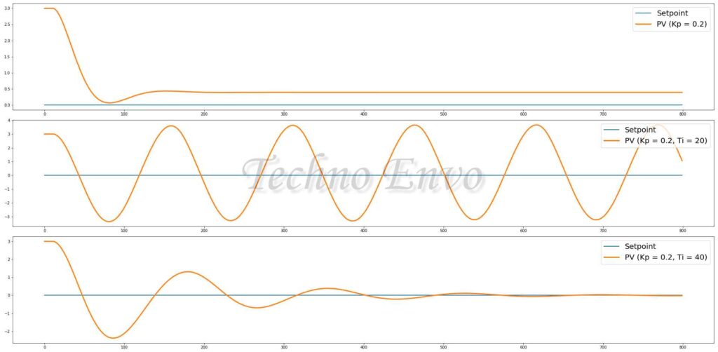
- Adjust Proportional Gain (P): This setting determines how strongly the controller reacts to current errors. High values increase responsiveness but can lead to oscillations.
- Set Integral Time (I): Integral time eliminates residual errors by considering past errors. Excessive values can cause sluggish responses.
- Define Derivative Time (D): Derivative time anticipates future errors to smooth the control response, helping to reduce overshoot and oscillations.
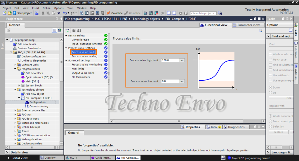
B. Define Safety and Output Constraints
- Set Minimum and Maximum Output: Limit the control output to safe values, protecting your system from extremes.
- Enable Anti-Windup: This feature prevents excessive integral accumulation, keeping the output within specified limits.
C. Fine-Tune the PID Parameters
- Manual Tuning: Start with low P, I, and D values and incrementally adjust them based on system response. Observing the process helps prevent oscillations or instability.
- Auto-Tuning (Optional): Some Siemens PLC models support auto-tuning, allowing the system to automatically adjust the PID values based on process feedback.
Step 4: Implementing and Testing the PID Control Loop
With the PID parameters configured, it’s time to implement the control loop and test it to ensure stable performance.
A. Simulate the PID Control Logic
- Run a Simulation in TIA Portal: Use TIA Portal’s simulation tools to test the PID logic before deploying it to the physical hardware.
- Monitor System Behavior: Confirm that the control output adjusts correctly to maintain the process variable at the setpoint.
B. Download the Program to the PLC
- Connect to the PLC: Ensure the PLC is connected to TIA Portal.
- Download the Program: Transfer the program to the PLC and test it in a real-world environment, observing how well the system maintains the setpoint.
Step 5: Real-World Application Examples
1. Temperature Control in an Industrial Oven
Industrial ovens require stable temperatures to ensure product quality. In this case, a Siemens PLC uses PID control to regulate temperature:
- Process Variable: Temperature inside the oven.
- Setpoint: Desired baking temperature.
- Control Action: Adjust heater power to maintain the set temperature.
2. Pressure Control in a Water Supply System
In water supply systems, maintaining constant pressure is essential to avoid damage and ensure efficient operation. A Siemens PLC can control valve positions through PID:
- Process Variable: Pressure level in the pipeline.
- Setpoint: Target pressure to meet operational standards.
- Control Action: Adjust the valve opening to regulate pressure.
FAQ: Implementing PID Control with Siemens PLCs
1. What is the main benefit of using PID control in industrial systems?
PID control provides precise and stable control over process variables, enabling more consistent production quality and energy efficiency. It’s particularly useful for managing critical variables like temperature, pressure, and flow.
2. How can I auto-tune PID parameters in Siemens PLCs?
Auto-tuning is available in certain Siemens PLC models. In TIA Portal, you can enable auto-tuning in the PID Compact block, which allows the system to calculate optimal PID settings based on real-time performance.
3. What should I do if my PID loop is oscillating?
If the system oscillates, reduce the Proportional Gain (P) or adjust the Derivative (D) setting to stabilize the response. Fine-tuning these parameters should reduce oscillations and improve control stability.
4. Can Siemens PLCs handle multiple PID loops?
Yes, Siemens PLCs are capable of handling multiple PID loops simultaneously, making them ideal for systems where multiple variables require control, such as in multi-zone temperature regulation.
5. Which industries benefit most from PID control?
Industries such as manufacturing, chemical processing, water treatment, HVAC, and food production rely heavily on PID control to ensure consistent product quality and optimize resource use.
6. Is it possible to implement PID control without using TIA Portal?
TIA Portal simplifies PID implementation with built-in libraries and simulation tools. While it’s technically possible to program PID control manually without TIA Portal, using TIA Portal offers a faster and more user-friendly approach.
7. How often should I tune my PID parameters?
PID parameters may need periodic tuning if the system experiences major changes in load, environmental conditions, or other variables. Regular monitoring helps identify if and when adjustments are needed.
Conclusion
Implementing PID control using Siemens PLCs can greatly enhance the efficiency and stability of industrial processes. By following this step-by-step guide, you’ll be able to configure and fine-tune PID control loops to meet the specific requirements of your application. With Siemens PLCs and TIA Portal, industrial PID control is accessible, efficient, and effective, making it an ideal solution for automation professionals looking to optimize process stability and quality.