Lecture 1 in CNC Programming Coordinate Systems in G-Code (G54–G59)
Introduction to CNC Programming
Every CNC programmer must understand coordinate systems. Without mastering them, it is impossible to machine a part accurately or safely. Whether you’re cutting a simple aluminum plate or machining a 5-axis aerospace component, coordinate systems determine where the machine thinks the tool is—and where it will move next.
This article will guide you through the fundamentals of CNC coordinate systems, including machine coordinates, work offsets, absolute vs. incremental positioning, G54–G59, and practical examples. You’ll also learn useful formulas, real G-code samples, and a beginner project.
1. What Are Coordinate Systems in CNC?
A coordinate system defines the tool’s position in X, Y, and Z axes. CNC machines use several coordinate systems simultaneously:
-
Machine Coordinates (G53)
-
Work Coordinates (G54–G59)
-
Absolute Programming (G90)
-
Incremental Programming (G91)
-
Tool Length Offsets (G43)
By combining these coordinate systems, the CNC machine calculates the final tool position.
2. CNC Machine Coordinates (G53)
Machine coordinates are fixed and defined by the manufacturer. They describe the physical limits and home position of the machine.
Example of machine home:
-
X = 0 at far left
-
Y = 0 at front
-
Z = 0 at the top of travel
When you reference or home the machine (usually called Machine Zero Return), it moves to this absolute origin.
Using G53 in G-Code in CNC Programming
G53 is non-modal, meaning it works only on the line where it appears.
Example:
:
This is useful for safe retraction before tool changes.
3. Work Coordinate Systems (G54–G59)
Work offsets are user-defined coordinate systems. You set them on the workpiece using a probe or reference edge.
The most common work offsets:
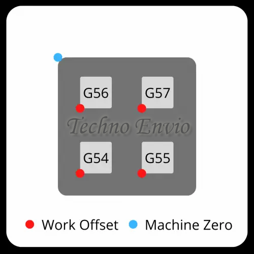
| Work Offset | Use |
|---|---|
| G54 | Main work offset |
| G55 | Secondary fixture |
| G56–G59 | Multi-part setups |
Why do we need them?
Because we don’t want to machine everything at machine zero.
Instead, we set the part’s zero point wherever is convenient:
-
Top of the part
-
Corner of the stock
-
Center of a round workpiece
4. How CNC Work Offsets Are Calculated
Let’s say your part zero is:
-
100 mm in X from machine home
-
50 mm in Y
-
40 mm in Z
Then:
The machine applies this internally:
Final Tool Position Formula
Actual Position=Machine Position+Work Offset\text{Actual Position} = \text{Machine Position} + \text{Work Offset}
So if you program:
The machine moves to:
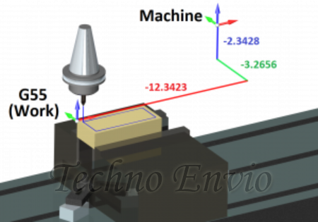
5. Visualizing Coordinate Systems
CNC Machine Coordinate Space:
Work Coordinate Space with G54:
The G54 origin can be anywhere on the table or part.
6. Absolute vs. Incremental CNC Programming (G90/G91)
Understanding these two modes is crucial.
G90 — Absolute Mode
All positions are measured from work offset zero.
Example:
Meaning:
Move to the absolute position (50, 20).
G91 — Incremental Mode
All movements are measured from current position.
Example:
Meaning:
Move +10 mm in X and –5 mm in Y relative to where you currently are.
Absolute vs. Incremental Comparison
| Command | Outcome |
|---|---|
| G90 G01 X20 | Move to X = 20 |
| G91 G01 X20 | Move +20 from wherever you are |
Formula for Incremental Movement
New Position=Current Position+Commanded Increment\text{New Position} = \text{Current Position} + \text{Commanded Increment}
7. Practical G-Code Example Using G54
Scenario:
Your part zero (G54) is at the top-left corner of a block.
Program:
This cuts a perfect 40 × 20 mm rectangle regardless of where the part is located on the table, because G54 shifts the coordinate system.
8. Using Multiple Work Offsets (G54, G55, G56…)
This is common for:
-
Multi-fixture production
-
Running 2, 4, or 6 parts at the same time
-
Machining symmetrical parts
-
High-volume manufacturing
Example: CNC Machining two parts in one setup
Each work offset has its own X/Y/Z zero point.
9. G-Code Example with Two Fixtures
G54 Part
G55 Part
The same program block runs twice—once in each coordinate system.
10. Tool Length Offsets (G43) and Z-Axis Accuracy
Even if X and Y coordinates are correct, the Z position depends heavily on tool length.
Example:
This applies tool length compensation stored in Offset #1.
✔ Z Position Formula
Zactual=Zcommand−Tool LengthZ_\text{actual} = Z_\text{command} – \text{Tool Length}
11. Safety Tips When Working with Coordinate Systems
✔ Always verify:
-
Work offset values (G54–G59)
-
Tool length offsets (H01, H02…)
-
Absolute vs. incremental modes
-
Z safe height before rapid moves
✔ Use G53 for safe machine retraction:
Prevents crashes from incorrect work offsets.
12. Beginner CNC Project (Practical Application) with Coordinate Systems
Project: CNC Machine Two Identical Plates Using G54 & G55
Goal:
Use two work offsets to machine two plates automatically without repositioning.
Step 1 — Set Work Offsets
-
Plate 1 → G54
-
Plate 2 → G55
Example offsets:
| Offset | X | Y | Z |
|---|---|---|---|
| G54 | 50 | 30 | 0 |
| G55 | 150 | 30 | 0 |
Step 2 — Write the CNC Program
What You Learned in This CNC Project
✔ How work offsets define separate coordinate spaces
✔ How to machine two parts without moving fixtures
✔ How G54 and G55 reduce setup time
✔ How to reuse the same toolpath efficiently
13. Conclusion
Understanding G54–G59 and positioning modes (G90/G91) is one of the most important skills in CNC programming. Work offsets make it possible to machine parts accurately and repeatedly without re-measuring everything. They also enable multi-part workflows, reduce production errors, and improve machining efficiency.
Once you fully understand coordinate systems, advanced topics like tool compensation, subs, macros, and multi-axis programming become much easier.