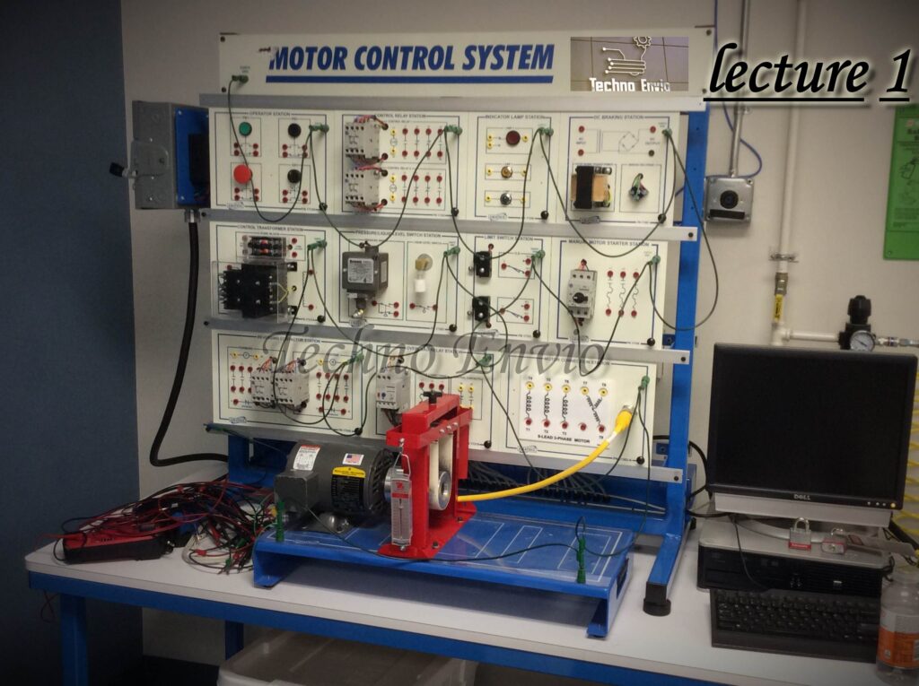
Part 1 Motor Principles: Magnetism, Electromagnetism, and Motor Rotation
Electric motors are at the heart of modern technology, powering everything from household appliances to industrial machines. To fully understand how motors work, it’s essential to explore the principles of magnetism, electromagnetism, and the interaction that produces motor rotation. This article will break down these concepts with equations, examples, and simple projects to help you grasp the fundamentals.
1. Motor Principle
At its core, a motor converts electrical energy into mechanical energy. This conversion relies on the interaction between magnetic fields and electric currents.
The fundamental principle behind motor operation can be summarized as:
“A current-carrying conductor in a magnetic field experiences a force.”
This force creates motion, which is harnessed to rotate the motor shaft.
The magnitude of this force can be calculated using Lorentz Force Law:

Where:
-
F= Force (Newtons)
-
B= Magnetic flux density (Tesla)
-
I= Current (Amperes)
-
L= Length of conductor in the magnetic field (meters)
-
sin(θ) = Angle between the conductor and the magnetic field
Example:
If a conductor of 0.2 m is carrying 5 A of current perpendicular to a 0.5 T magnetic field, the force is:
2. Magnetism
Magnetism is the force exerted by magnets when they attract or repel each other. In motors, magnets (permanent or electromagnets) create the magnetic field necessary for motion.
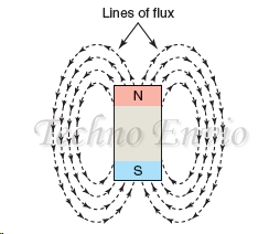
Key concepts:
-
Magnetic Field (B): The area around a magnet where magnetic forces are felt.
-
Magnetic Poles: North and South poles attract opposite poles and repel the same poles.
Mini Project:
Take a small bar magnet and a compass. Move the magnet around the compass and observe how the needle aligns with the magnetic field. This simple experiment demonstrates how magnetic fields interact with materials.
3. Electromagnetism
Electromagnetism combines electricity and magnetism. When an electric current passes through a conductor, it generates a magnetic field around it. This principle is fundamental for motor operation.
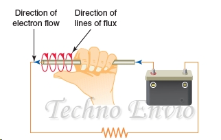
Right-Hand Rule:
Point your right thumb in the direction of current; your fingers curl in the direction of the magnetic field.
Equation for Magnetic Field around a straight conductor:
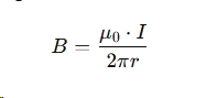
Where:
-
= Magnetic field (Tesla)
-
= Permeability of free space (4π×10−7 H/m4\pi \times 10^{-7} \, \text{H/m})
-
I = Current (Amperes)
-
r = Distance from the conductor (meters)
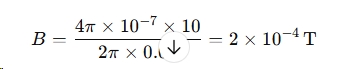
Example:
For a wire carrying 10 A of current, the magnetic field at 0.01 m distance is:
Project Idea:
Create a simple electromagnet by wrapping copper wire around a nail and connecting it to a battery. Test its ability to pick up paperclips. Experiment by changing the number of wire turns or battery voltage.
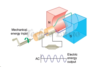
4. Generators
Generators operate on the reverse principle of motors: mechanical energy is converted into electrical energy. However, the basic concept of electromagnetic induction is the same.
Faraday’s Law of Induction:
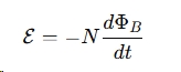
Where:
-
E = Induced voltage (Volts)
-
N = Number of turns in the coil
-
= Magnetic flux (Weber)
Example:
Rotating a coil with 50 turns in a changing magnetic flux of 0.02 Wb/s generates:
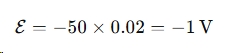
This voltage can power circuits or charge batteries. Understanding generators helps comprehend the feedback effect in motor control systems.
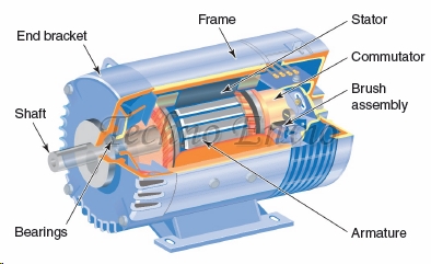
5. Motor Rotation
The rotation of a motor is the result of the force acting on current-carrying conductors within a magnetic field.
Key components include:
-
Stator: Stationary part generating a magnetic field
-
Rotor: Rotating part that experiences force
-
Commutator (in DC motors): Reverses current direction to maintain continuous rotation
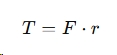
Torque Equation:
Where:
-
= Torque (Nm)
-
= Force on conductor (N)
-
= Radius from rotation axis (m)
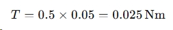
Practical Example:
A rotor experiences 0.5 N of force at 0.05 m from the axis. Torque is:
Mini Project:
Build a simple homemade DC motor using a battery, copper wire, and small magnets. Observe how changing the wire loops or battery voltage affects speed and torque.
Conclusion Part 1
Understanding motors requires a grasp of magnetism, electromagnetism, and rotation principles. With these foundations, you can design experiments, build small projects, or troubleshoot industrial motors. Incorporating equations and hands-on examples makes learning not only practical but also fun.
By following these principles, beginners and enthusiasts can develop real-world skills, laying the groundwork for advanced motor and electrical engineering studies
Part 2 Direct Current (DC) Motors: Types, Principles, and Applications
DC motors are fundamental components in modern electronics and industrial automation. They convert direct current electrical energy into mechanical motion and are widely used in robotics, conveyor systems, and precision devices. This article explores types of DC motors, their operation, performance characteristics, and speed control methods, complete with formulas, examples, and mini-project ideas.
1. Direct Current Motors
A DC motor works on the principle that a current-carrying conductor experiences a force in a magnetic field, producing torque. The general equation for torque in a DC motor is:
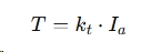
Where:
-
= Torque (Nm)
-
= Torque constant (Nm/A)
-
= Armature current (A)
DC motors are classified into several types based on how the field winding is connected:
-
Permanent-Magnet DC Motor
-
Series DC Motor
-
Shunt DC Motor
-
Compound DC Motor
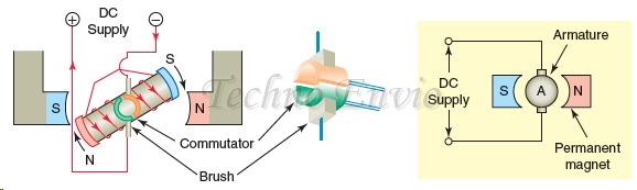
2. Permanent-Magnet DC Motor (PMDC)
PMDC motors use permanent magnets instead of field windings to produce the magnetic field. They are compact, efficient, and ideal for low-power applications.
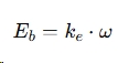
Key equation – Back EMF (Counter Electromotive Force):
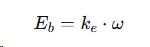
Where:
-
= Back EMF (V)
-
= Voltage constant
-
ω = Angular speed (rad/s)
Example:
If a PMDC motor has a voltage constant = 0.02 V/rad/s and rotates at 300 rad/s:
Mini Project Idea:
Use a small PMDC motor to build a battery-powered fan. Measure how increasing voltage affects speed.
3. Series DC Motor
In a series DC motor, the field winding is in series with the armature. This gives high starting torque, making it ideal for heavy loads like cranes or traction systems.
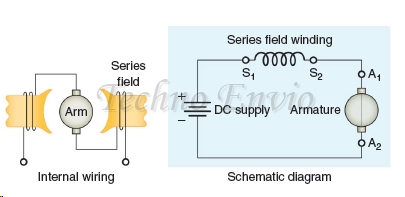
Key characteristics:
-
Torque is proportional to the square of armature current:

-
Speed decreases as load increases.
Example:
A series DC motor with armature current 10 A produces torque:
![]()
Mini Project Idea:
Connect a series DC motor to a variable resistor and observe how the speed changes with load.
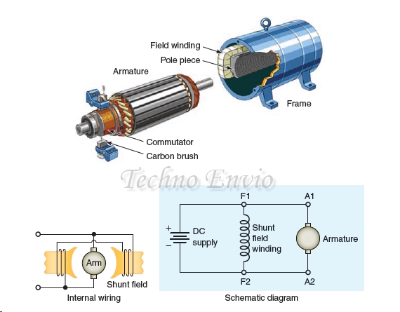
4. Shunt DC Motor
In shunt DC motors, the field winding is connected in parallel with the armature. This provides better speed regulation and stable operation under varying loads.
Speed Equation:
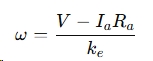
Where:
-
V = Applied voltage (V)
-
= Armature resistance (Ω)
Example:
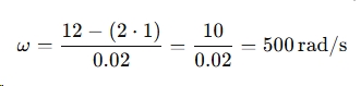
For a shunt motor with V = 12 V , Ia = 2 A, Ra = 1 Ω, and ke = 0.02 V/rad/s:
Mini Project Idea:
Build a small shunt motor speed controller using a potentiometer and observe stable speed under varying loads.
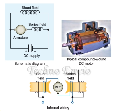
5. Compound DC Motor
Compound DC motors combine series and shunt windings to get both high starting torque and good speed regulation. They are used in elevators and rolling mills.
Key Points:
-
Torque and speed characteristics are a combination of series and shunt types.
-
Ideal for applications needing both torque and stability.
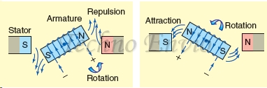
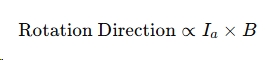
6. Direction of Rotation
The direction of a DC motor depends on the current flow in the armature and field windings.
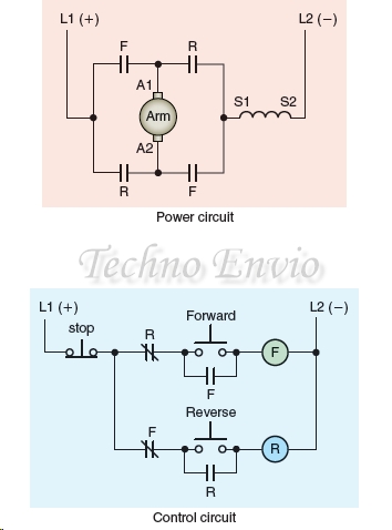
Reversing either the armature or field current reverses the rotation:
Mini Project:
Wire a PMDC motor with a DPDT switch to reverse current and change rotation direction.
7. Motor Counter Electromotive Force (CEMF)
As a motor spins, it generates back EMF (CEMF) opposing the applied voltage:
-
Back EMF reduces armature current at high speeds.
-
Important for speed regulation and motor protection.
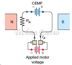
Example:
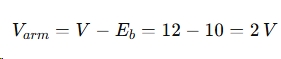
If applied voltage is 12 V and CEMF is 10 V, the effective voltage across the armature is:
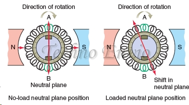
8. Armature Reaction
Armature current produces a magnetic field that can distort the main field, affecting torque and efficiency.
-
Compensating windings or interpole design are used in industrial motors to reduce this effect.
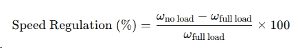
9. Speed Regulation
Shunt motors: Good speed regulation ( with load)
Series motors: Poor speed regulation (speed drops significantly under load)
Equation for shunt motor speed regulation:
10. Varying DC Motor Speed
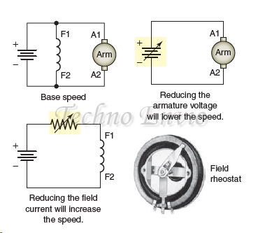
DC motor speed can be controlled by:
-
Armature voltage control: Vary applied to armature.
-
Field flux control: Adjust field winding current.
-
PWM Drives: Use electronic pulse width modulation for precise control.
Mini Project:
Use an Arduino with PWM output to control a small PMDC motor. Vary the duty cycle to change speed and plot the speed vs duty cycle curve.
11. DC Motor Drives
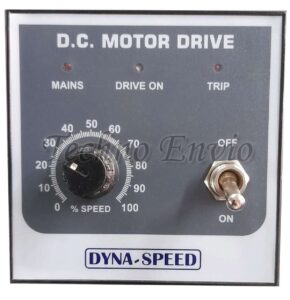
Modern DC motor drives use semiconductors and microcontrollers to achieve:
-
Smooth acceleration and deceleration
-
Efficient energy use
-
Closed-loop control for robotics and automation
Equation for DC motor drive current:
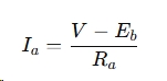
Where can be monitored and controlled by a microcontroller for safety and efficiency.
Conclusion Part 2
Understanding DC motors involves studying types, back EMF, torque, speed regulation, and control methods. By combining theory, equations, and hands-on projects, beginners and engineers can master DC motor applications from robotics to industrial automation.