Part 7 Motor Installation: Best Practices for Reliable Operation
Proper motor installation is critical for efficient operation, long service life, and safety. Even the best motor can fail prematurely if installed incorrectly. This guide covers foundation, mounting, alignment, electrical connections, grounding, conductor sizing, voltage balance, and built-in protection for motors.
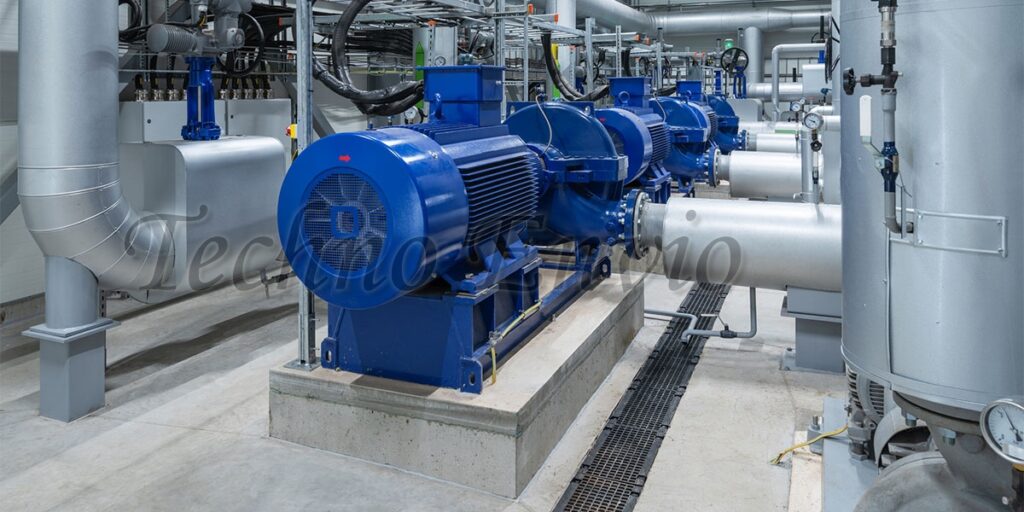
1. Motor Foundation
The motor foundation is the structural base that supports the electric motor and its driven equipment. A properly designed foundation is critical for mechanical stability, vibration control, accurate alignment, and long service life of both the motor and the load.
Poor foundations are one of the most common root causes of vibration, bearing failure, shaft misalignment, and premature motor damage.
Purpose of a Motor Foundation
A good foundation must:
-
Support the combined weight of motor and load
-
Withstand dynamic forces and torque
-
Maintain alignment under operating conditions
-
Minimize vibration and noise
-
Prevent movement, settling, or distortion
Types of Motor Foundations
1. Motor Concrete Foundation
The most common and recommended type for industrial motors.
Advantages:
-
High rigidity and mass
-
Excellent vibration damping
-
Long service life
Best Practices:
-
Foundation mass should be 2–3 times the motor and load mass
-
Use reinforced concrete
-
Allow sufficient curing time before installation
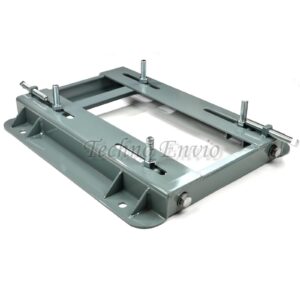
2. Motor Steel Base or Frame
Used when concrete foundations are not practical.
Applications:
-
Skid-mounted equipment
-
Portable systems
-
Light to medium-duty motors
Considerations:
-
Must be rigid and properly braced
-
Avoid thin or flexible steel plates
-
Anchor securely to floor or structure
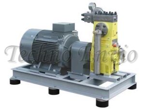
3. Machine Base or Skid
Motor and load are mounted on a common base.
Advantages:
-
Factory alignment possible
-
Reduced installation time
Limitations:
-
Limited vibration absorption
-
Requires careful leveling and anchoring
Motor Foundation Design Considerations
Load and Torque Forces
The foundation must handle:
-
Static load (motor + equipment weight)
-
Dynamic load (starting torque, load variations)
-
Shock loads (frequent starts, stops, or reversing)
Vibration and Resonance Control
Excessive vibration causes:
-
Bearing damage
-
Loosening of fasteners
-
Fatigue cracks
Prevention Methods:
-
Increase foundation mass
-
Avoid resonance between motor speed and foundation natural frequency
-
Use inertia blocks for high-speed motors
Motor Leveling and Flatness
-
Foundation surface must be flat and level
-
Use precision leveling tools
-
Uneven surfaces cause soft foot and frame distortion
Anchor Bolts and Grouting
Anchor Bolts
-
Secure the base to the foundation
-
Prevent movement during operation
Types:
-
J-bolts
-
L-bolts
-
Expansion anchors
Grouting
Grout fills the gap between base plate and foundation.
Functions:
-
Transfers load evenly
-
Prevents moisture ingress
-
Increases rigidity
Best Practices:
-
Use non-shrink grout
-
Clean surfaces before grouting
-
Allow full curing before final alignment
Motor Foundation Preparation Steps
-
Construct and cure foundation
-
Install anchor bolts
-
Place base plate or motor
-
Level and shim
-
Apply grout
-
Tighten anchor bolts
-
Perform final alignment
Common Motor Foundation Problems
-
Insufficient mass
-
Poor curing
-
Cracked concrete
-
Loose anchor bolts
-
Uneven surface
-
Inadequate grouting
These issues lead to misalignment, vibration, and premature motor failure.
Motor Foundation Inspection and Maintenance
-
Periodically inspect for cracks
-
Check anchor bolt tightness
-
Monitor vibration levels
-
Re-verify alignment after foundation repairs
2. Mounting
Motor mounting refers to the method and physical arrangement used to secure an electric motor to its foundation or driven equipment. Proper mounting ensures mechanical stability, correct alignment, vibration control, and safe operation throughout the motor’s service life.
Incorrect mounting is a major cause of vibration, misalignment, bearing failure, and structural damage.
Objectives of Proper Motor Mounting
Correct mounting:
-
Provides rigid mechanical support
-
Maintains shaft alignment
-
Minimizes vibration and noise
-
Prevents frame distortion
-
Supports motor weight and torque
-
Ensures safe operation under load
Common Motor Mounting Types
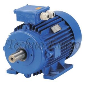
1. Foot-Mounted Motors (Horizontal Mounting)
The motor is mounted on a base or foundation using mounting feet.
Applications:
-
Pumps
-
Fans
-
Compressors
-
Conveyors
Best Practices:
-
Use a flat, rigid base
-
Ensure all feet contact the surface
-
Check for soft foot before alignment
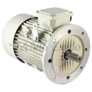
2. Flange-Mounted Motors
Motor is mounted directly to the driven equipment using a flange.
Applications:
-
Gearboxes
-
Pumps
-
Machine tools
Advantages:
-
Compact design
-
Accurate shaft positioning
Precautions:
-
Ensure flange faces are clean and square
-
Avoid excessive axial loads
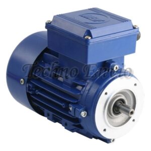
3. Face-Mounted Motors
Similar to flange mounting but with a larger face contact area.
Applications:
-
Precision machinery
-
Servo and positioning systems
4. Vertical Mounting
Motor shaft is oriented vertically.
Applications:
-
Vertical pumps
-
Mixers
-
Cooling towers
Considerations:
-
Bearing type must support axial load
-
Proper lubrication is critical
Mounting Surface and Base Requirements
The mounting surface must:
-
Be rigid and level
-
Withstand vibration and torque
-
Prevent base deformation
Poor base quality causes:
-
Frame distortion
-
Misalignment
-
Bearing overheating
Bolt Selection and Tightening
-
Use correct bolt size and grade
-
Tighten bolts evenly and diagonally
-
Follow manufacturer torque values
-
Recheck bolt tightness after initial operation
Loose bolts increase vibration and misalignment.
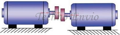
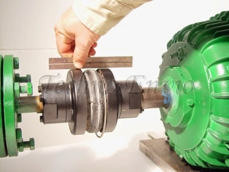
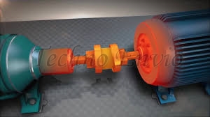
3. Motor and Load Alignment
Motor and load alignment is the process of positioning the motor shaft and the driven equipment shaft (pump, gearbox, fan, compressor, conveyor, etc.) so that their centerlines coincide during operation. Proper alignment is essential for efficient power transmission, reduced vibration, and long motor life.
Poor alignment is one of the leading causes of premature bearing, coupling, and seal failures in industrial motor systems.
Importance of Proper Alignment
Correct motor and load alignment:
-
Reduces bearing and coupling wear
-
Minimizes vibration and noise
-
Prevents shaft and seal damage
-
Improves energy efficiency
-
Extends motor and equipment lifespan
-
Reduces unplanned downtime
Even small misalignment can significantly shorten bearing life.
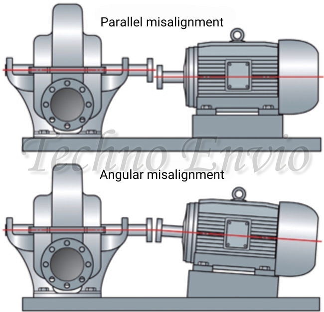
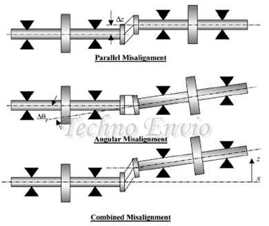
Types of Misalignment
1. Parallel (Offset) Misalignment
Shafts are parallel but not in the same centerline.
Effects:
-
Uneven bearing loading
-
Increased vibration
-
Accelerated coupling wear
2. Angular Misalignment
Shaft centerlines intersect at an angle.

Effects:
-
Axial thrust on bearings
-
Seal damage
-
Increased motor temperature
3. Combined Misalignment
A combination of parallel and angular misalignment.
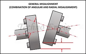
Effects:
-
Severe vibration
-
Rapid mechanical failure
-
High maintenance costs
Common Causes of Misalignment
-
Improper installation
-
Soft foot condition
-
Thermal expansion differences
-
Pipe strain on pumps
-
Worn or damaged couplings
-
Foundation movement or settling
Alignment must consider operating conditions, not just static setup.
Alignment Methods
1. Straightedge and Feeler Gauge
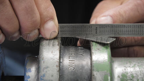
Advantages:
-
Low cost
-
Simple to use
Limitations:
-
Low accuracy
-
Suitable only for small, non-critical machines
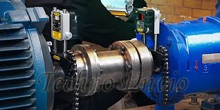
2. Dial Indicator Method
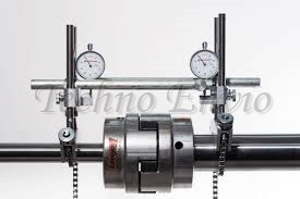
Advantages:
-
High accuracy
-
Industry-accepted standard
Limitations:
-
Requires experience
-
Time-consuming

3. Laser Shaft Alignment
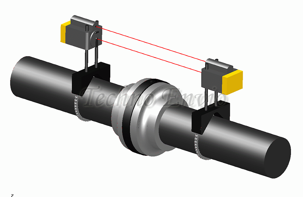
Advantages:
-
Highest accuracy
-
Fast and repeatable
-
Ideal for critical equipment
Limitations:
-
Higher initial cost
Soft Foot and Its Impact
Soft foot occurs when one or more motor feet do not sit flat on the base.
Effects:
-
Frame distortion
-
Bearing misalignment
-
Increased vibration
Correction:
-
Shim adjustment
-
Base surface inspection
Soft foot must be corrected before final alignment.
Alignment Tolerances
Acceptable alignment limits depend on:
-
Motor speed (RPM)
-
Shaft size
-
Coupling type
-
Manufacturer specifications
High-speed motors require tighter alignment tolerances.
Common Alignment Tolerance Standards
General Industry Guidelines (Flexible Couplings)
| Motor Speed (RPM) | Parallel Offset (mm) | Angular Misalignment (mm / 100 mm) |
|---|---|---|
| Up to 1,750 | ≤ 0.10 mm | ≤ 0.10 mm |
| 1,750 – 3,600 | ≤ 0.05 mm | ≤ 0.05 mm |
| Above 3,600 | ≤ 0.03 mm | ≤ 0.03 mm |
⚠ Always follow coupling manufacturer limits if they are more restrictive.
Thermal Growth Considerations
During operation, motors and driven equipment expand due to heat.
Example
A motor operating at 80°C may grow:
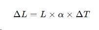
Where:
-
L = shaft length (m)
-
= coefficient of thermal expansion
-
= temperature rise
Cold alignment must compensate for hot operating conditions, especially in pumps and compressors.
Alignment Methods and Accuracy for Motor
1. Straightedge and Feeler Gauge
-
Accuracy: ±0.1 mm
-
Suitable for low-speed, non-critical equipment
2. Dial Indicator Method
-
Accuracy: ±0.02 mm
-
Widely used in industrial maintenance
3. Laser Alignment Systems
-
Accuracy: ±0.001 mm
-
Recommended for high-speed and critical machinery
Soft Foot Impact on Tolerances
Soft foot occurs when one or more motor feet do not sit flat.
Effects:
-
Distorted alignment readings
-
Frame stress
-
Bearing misalignment after tightening
Soft foot must be corrected before final alignment.
Coupling Type and Tolerance
| Coupling Type | Tolerance Capability |
|---|---|
| Rigid coupling | Very low tolerance |
| Elastomeric coupling | Moderate tolerance |
| Gear coupling | Higher tolerance |
| Disc coupling | Low angular tolerance |
Flexible couplings do not eliminate the need for proper alignment.
Alignment Verification
Alignment should be checked:
-
After installation
-
After grouting
-
After initial run-in
-
During scheduled maintenance
-
After bearing or coupling replacement
Practical Industrial Example
Pump Motor Alignment
-
Speed: 2,900 RPM
-
Required tolerance: ≤ 0.05 mm
-
Method used: Laser alignment
-
Result: Vibration reduced by 60%, bearing life doubled
Thermal Growth Considerations
During operation, motors and driven equipment expand due to heat.
Best Practice:
-
Apply cold alignment offsets
-
Consider operating temperature differences
Ignoring thermal growth leads to misalignment during normal operation.
Coupling Selection and Alignment
Flexible couplings tolerate minor misalignment but do not eliminate the need for proper alignment.
Rigid couplings require very precise alignment.
Symptoms of Poor Alignment
-
Excessive vibration
-
Abnormal bearing noise
-
Coupling wear
-
Seal leakage
-
High motor current
-
Increased operating temperature
4. Motor Bearings
Motor bearings support the rotor shaft and allow it to rotate smoothly with minimal friction. They play a critical role in motor efficiency, noise level, vibration control, and service life. Bearing failure is one of the most common causes of electric motor breakdowns in industrial environments.
Functions of Motor Bearings
Motor bearings are designed to:
-
Support rotor weight
-
Maintain correct air gap between rotor and stator
-
Reduce mechanical friction
-
Minimize vibration and noise
-
Handle radial and axial loads
A damaged bearing can quickly lead to shaft misalignment, rotor rubbing, and winding failure.
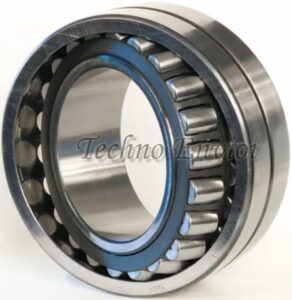
Types of Motor Bearings
1. Ball Bearings
The most widely used bearing type in electric motors.
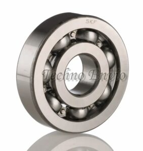
Characteristics:
-
Low friction
-
Suitable for high-speed operation
-
Moderate radial and axial load capacity
Common Applications:
-
Pumps
-
Fans
-
Compressors
-
General-purpose motors
2. Roller Bearings
Roller bearings are used when higher load capacity is required.
Cylindrical Roller Bearings
-
High radial load capacity
-
Limited axial load capability
Tapered Roller Bearings
-
Handle combined radial and axial loads
-
Often used in large motors
3. Sleeve (Journal) Bearings
Used mainly in large motors and turbines.
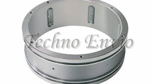
Characteristics:
-
Shaft rides on a thin oil film
-
Very quiet operation
-
Excellent for heavy loads
Limitations:
-
Require continuous lubrication
-
Sensitive to contamination
Bearing Load Types
Radial Load
-
Acts perpendicular to shaft
-
Common in belt-driven systems
Axial (Thrust) Load
-
Acts along shaft axis
-
Common in vertical motors and pumps
Correct bearing selection depends on load type and magnitude.
Bearing Lubrication
Proper lubrication is critical to bearing life.
Lubrication Types:
-
Grease-lubricated bearings
-
Oil-lubricated bearings
Common Lubrication Errors:
-
Over-greasing (causes overheating)
-
Under-lubrication
-
Using incorrect grease type
-
Mixing incompatible greases
Bearing Seals and Shields
Bearings are protected by:
-
Metal shields (ZZ)
-
Rubber seals (2RS)
Purpose:
-
Prevent dust and moisture ingress
-
Retain lubricant inside the bearing
Harsh environments require sealed or protected bearings.
Bearing Failure Causes
-
Improper lubrication
-
Shaft misalignment
-
Excessive belt tension
-
Electrical shaft currents (VFD applications)
-
Contamination (dust, water, chemicals)
Bearing Failure Symptoms
-
Abnormal noise
-
Increased vibration
-
Rising motor temperature
-
Shaft play
-
Grease leakage
Early detection prevents secondary motor damage.
Bearing Protection in VFD Applications
VFDs can induce shaft currents that damage bearings.
Protection Methods:
-
Insulated bearings
-
Shaft grounding rings
-
Proper cable shielding
Bearing Maintenance Best Practices
-
Follow manufacturer lubrication intervals
-
Use vibration analysis
-
Monitor bearing temperature
-
Inspect seals regularly
-
Avoid excessive belt or coupling force
Practical Industrial Example
Application: Conveyor Motor
Problem: Loud noise and vibration
Cause: Bearing wear due to over-greasing
Solution: Bearing replacement and proper lubrication schedule
Result: Smooth operation and extended motor life
5. Electrical Connections
Correct electrical connections are essential for the safe, efficient, and reliable operation of electric motors. Poor connections are a common cause of overheating, voltage imbalance, nuisance tripping, and unexpected motor failure. Proper installation ensures the motor receives the correct voltage and current while complying with electrical safety standards.
Types of Motor Electrical Connections
Electric motors can be connected in different configurations depending on:
-
Supply voltage
-
Motor design
-
Starting method
1. Single-Phase Motor Connections
Single-phase motors typically include:
-
Main (run) winding
-
Auxiliary (start) winding
-
Capacitor (start/run)
Key Points:
-
Correct polarity and capacitor rating are critical
-
Incorrect wiring causes poor starting torque or overheating
2. Three-Phase Motor Connections
Three-phase motors are connected using either:
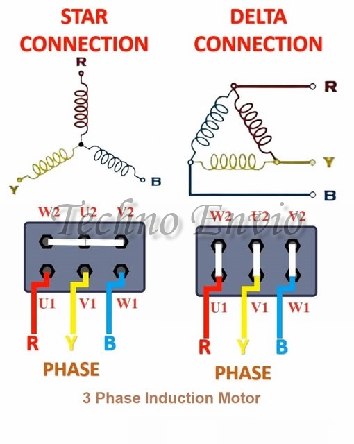
Star (Y) Connection
-
Used for higher voltage
-
Lower starting current
-
Lower starting torque
Delta (Δ) Connection
-
Used for lower voltage
-
Higher starting torque
-
Higher starting current
Star–Delta Example
A motor rated 400/690 V:
-
Delta at 400 V
-
Star at 690 V
Incorrect connection can burn motor windings.
Terminal Box and Nameplate
Motor terminal boxes contain:
-
Connection terminals
-
Jumpers or links
-
Ground terminal
Always follow:
-
Motor nameplate diagram
-
Manufacturer wiring instructions
Phase Sequence and Direction of Rotation
Motor rotation depends on phase sequence.
Rotation Change:
-
Swap any two phases
-
Applicable only to three-phase motors
Incorrect rotation can damage:
-
Pumps
-
Compressors
-
Conveyors
Cable Termination and Lugs
Use:
-
Properly sized cable lugs
-
Crimping tools
-
Insulated terminations
Poor termination leads to:
-
Arcing
-
Heat buildup
-
Connection failure
Connection to Starters and Drives
Direct-On-Line (DOL) Starter
-
Simple connection
-
High inrush current
Star–Delta Starter
-
Requires six motor leads
-
Proper timing between star and delta
VFD Connection
-
Motor must be wired directly to drive output
-
Never switch motor output while VFD is running
Insulation and Clearance
Ensure:
-
No exposed conductors
-
Adequate phase-to-phase clearance
-
Proper cable glands to prevent dust and moisture ingress
Electrical Safety and Lockout

Before making connections:
-
Isolate power supply
-
Apply lockout/tagout (LOTO)
-
Verify absence of voltage
Safety procedures prevent serious accidents.
Common Electrical Connection Errors
-
Incorrect star/delta configuration
-
Loose terminal screws
-
Undersized lugs
-
Wrong phase sequence
-
Shared neutral or ground paths
6. Grounding
Grounding (earthing) is one of the most critical safety requirements in electric motor installation. Proper grounding protects people, equipment, and electrical systems by providing a low-impedance path for fault currents and stabilizing system voltage during abnormal conditions.
Poor or missing grounding can lead to electric shock, fire hazards, bearing damage, and unreliable motor operation.
Purpose of Motor Grounding
Motor grounding serves several essential functions:
-
Protects personnel from electric shock
-
Enables fast operation of protective devices
-
Prevents excessive touch voltage on motor frames
-
Reduces electrical noise and interference
-
Protects bearings from circulating currents (especially with VFDs)
Grounding vs Bonding
| Term | Description |
|---|---|
| Grounding | Connection to earth |
| Bonding | Connecting all metal parts together |
Both are required for a safe motor installation.
Motor Grounding Components
1. Equipment Grounding Conductor (EGC)
The equipment grounding conductor connects:
-
Motor frame
-
Conduit
-
Junction boxes
-
Control panels
to the grounding system.
It carries fault current during a ground fault, allowing the breaker to trip quickly.
2. Grounding Electrode System for Motor
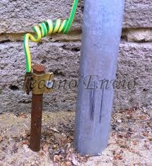
This includes:
-
Ground rods
-
Ground grids
-
Building steel
-
Concrete-encased electrodes
Motors are indirectly connected through the electrical system grounding.
Grounding the Motor Frame
All motor metallic parts must be grounded:
-
Motor housing
-
Terminal box
-
Mounting base
Ground connections should be:
-
Clean (paint removed)
-
Tight and corrosion-free
-
Periodically inspected
Grounding and Overcurrent Protection
Proper grounding ensures that during a fault:

A poor ground path limits fault current, preventing breakers from operating and increasing fire risk.
Grounding for VFD-Driven Motors
VFDs introduce high-frequency voltages that require special grounding practices.
Best Practices:
-
Use short, wide ground conductors
-
Bond motor frame directly to drive ground
-
Avoid shared grounding paths
-
Use shielded motor cables when possible
Bearing Protection
High-frequency currents can damage bearings.
Solutions:
-
Insulated bearings
-
Shaft grounding rings
-
Proper grounding conductors
Ground Conductor Sizing
Ground conductor size depends on:
-
Overcurrent device rating
-
Electrical code requirements
Ground conductors are not sized the same as phase conductors.
Grounding and EMI Reduction
Proper grounding:
-
Reduces electromagnetic interference (EMI)
-
Improves PLC and sensor signal stability
-
Prevents nuisance trips and communication errors
Common Grounding Mistakes
-
Using conduit as the only ground path
-
Loose or corroded ground connections
-
Sharing grounding with sensitive electronics
-
Ignoring VFD grounding recommendations
Practical Industrial Example
Application: Pump Motor with VFD
Problem:
-
Frequent VFD faults
-
Bearing failure every 6 months
Solution:
-
Dedicated grounding conductor
-
Shaft grounding ring
-
Shielded motor cable
Result:
-
Faults eliminated
-
Bearing life extended
Motor Inspection and Testing
Recommended checks:
-
Continuity test of ground conductor
-
Ground resistance measurement
-
Visual inspection of connections
Regular inspection ensures long-term safety.
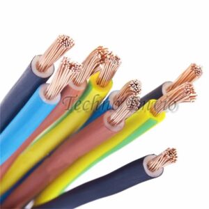
7. Conductor Size for Motor
Correct conductor (cable) sizing is essential for the safe, efficient, and reliable operation of electric motors. Undersized conductors cause overheating, voltage drop, nuisance tripping, and premature motor failure, while oversized conductors increase cost without added benefit.
Purpose of Proper Conductor Sizing
Motor conductors must be sized to:
-
Carry continuous full-load current
-
Withstand starting (inrush) current
-
Limit voltage drop
-
Comply with NEC / IEC electrical codes
Motor Full-Load Current (FLC)
Conductor size is based on motor full-load current, not horsepower alone.
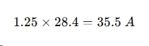
NEC Guideline (Concept):
Motor branch-circuit conductors must be sized at 125% of motor FLC.

Example Calculation
Motor:
-
Power: 15 kW
-
Voltage: 400 V
-
Efficiency: 90%
-
Power factor: 0.85
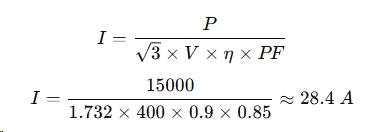
Required conductor current:
Voltage Drop Considerations
Excessive voltage drop reduces motor torque and increases current.
Recommended Limits:
-
≤ 3% for branch circuits
-
≤ 5% total system drop
Voltage Drop Formula (Three-Phase):
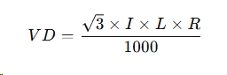
Where:
-
I = Current (A)
-
L = One-way cable length (m)
-
R = Resistance per km (Ω/km)
Starting Current and Thermal Stress
Motor starting current can be 5–8 times FLC.
Although conductors are sized for FLC:
-
Insulation must withstand starting current
-
Proper breaker coordination is required
Insulation Type and Temperature Rating
Common insulation types:
-
PVC (70°C)
-
XLPE (90°C)
Higher temperature insulation allows:
-
Smaller conductor size
-
Higher current capacity
Ambient Temperature Correction
High ambient temperature reduces conductor ampacity.
Example:
At 50°C ambient, conductor capacity may reduce by 15–20%.
Always apply correction factors when required.
Installation Method
Conductor ampacity depends on:
-
Conduit or cable tray
-
Number of current-carrying conductors
-
Ventilation conditions
Bundled cables generate more heat and require derating.
Copper vs Aluminum Conductors
| Parameter | Copper | Aluminum |
|---|---|---|
| Conductivity | High | Lower |
| Size | Smaller | Larger |
| Weight | Heavy | Light |
| Cost | Higher | Lower |
Aluminum conductors must be properly terminated to avoid overheating.
Grounding Conductor Size
Ground conductors are sized based on:
-
Overcurrent protection rating
-
Electrical code requirements
Grounding does not replace neutral conductors.
Practical Industrial Motor Example
Application: Conveyor Motor
-
Motor: 11 kW, 400 V
-
Distance: 60 m
-
Environment: Industrial plant
Selected:
-
Copper cable
-
XLPE insulation
-
Sized for 125% FLC
-
Voltage drop within 3%
Result: Stable operation and long service life.
Common Mistakes
-
Using nameplate current without correction
-
Ignoring voltage drop
-
Not applying temperature derating
-
Undersizing aluminum conductors
-
Incorrect grounding conductor size
8. Voltage Levels and Balance for Motor
Correct voltage level and voltage balance are critical for the safe, efficient, and long-term operation of electric motors, especially three-phase motors. Even small deviations can cause overheating, torque loss, vibration, and premature motor failure.
Importance of Correct Voltage Level
Electric motors are designed to operate at a rated voltage (for example, 400 V, 415 V, or 460 V). Operating outside this range negatively affects performance.
Acceptable Voltage Tolerance
Most standards allow:
-
±10% of rated voltage
-
±5% voltage imbalance (maximum recommended)
Effects of Low Voltage
Low voltage reduces motor torque and increases current.
Torque–Voltage Relationship:

Example:
If voltage drops to 90% of rated value:
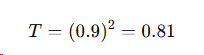
→ Torque drops to 81%
Consequences:
-
Motor draws higher current
-
Overheating
-
Nuisance tripping
-
Failure to start heavy loads
Effects of High Voltage
Excess voltage causes:
-
Increased magnetic flux
-
Core saturation
-
Higher iron losses
Consequences:
-
Excessive heating
-
Increased noise and vibration
-
Insulation stress
-
Shortened motor life
Voltage Balance in Three-Phase Systems
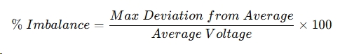
Voltage balance means all three phase voltages are equal.
Voltage Imbalance Formula:
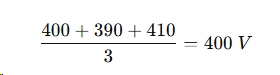
Example Calculation:
Measured voltages:
-
L1–L2 = 400 V
-
L2–L3 = 390 V
-
L3–L1 = 410 V
Average voltage:
Maximum deviation:
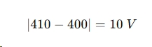
Voltage imbalance:
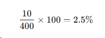
⚠️ Even 2–3% imbalance can cause serious motor heating.
Impact of Voltage Imbalance on Motors
A small voltage imbalance results in a much larger current imbalance.
Rule of Thumb:
-
1% voltage imbalance → 6–10% current imbalance
Effects:
-
Unequal phase heating
-
Rotor overheating
-
Reduced torque
-
Increased losses
Common Causes of Voltage Imbalance
-
Uneven single-phase loads
-
Loose or corroded connections
-
Blown fuses
-
Poor transformer tap settings
-
Unbalanced supply from utility
Voltage Balance and VFD-Driven Motors
For motors powered by Variable-Frequency Drives (VFDs):
-
Input voltage imbalance stresses rectifier diodes
-
DC bus voltage fluctuations increase
-
Drive may trip on undervoltage or overcurrent
Proper line reactors and supply quality are essential.
Motor Measurement and Monitoring
Best Practices:
-
Measure voltage at motor terminals
-
Record values during full load
-
Use true RMS meters
-
Monitor trends over time
Recommended Corrective Actions
| Problem | Solution |
|---|---|
| Low voltage | Upgrade conductors, reduce load |
| High voltage | Adjust transformer taps |
| Imbalance | Redistribute loads |
| Frequent trips | Install line reactors |
Practical Industrial Motor Example
Application: 30 kW Induction Motor
-
Voltage imbalance measured: 3%
-
Motor temperature increased by 15°C
-
Solution: Load redistribution and terminal tightening
-
Result: Temperature normalized, efficiency improved
9. Built-in Thermal Protection
Built-in thermal protection is an internal safety feature designed to protect electric motors from overheating and thermal damage. It continuously monitors motor temperature and automatically triggers a protective action when unsafe conditions occur.
Overheating is one of the leading causes of motor failure, making thermal protection essential for long motor life and reliable operation.
Why Motors Overheat
Motor temperature can rise due to several operating conditions:
-
Overloading
-
Frequent starting and stopping
-
Voltage imbalance or low voltage
-
Poor ventilation or blocked cooling
-
High ambient temperature
-
Bearing failure or mechanical friction
If not detected early, overheating causes insulation breakdown, leading to short circuits and motor burnout.
Types of Built-in Thermal Protection
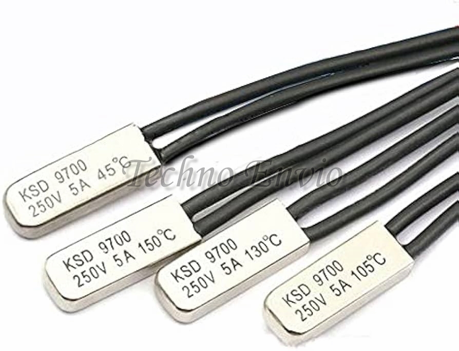
1. Thermal Overload Protector (Bimetal)
A bimetallic thermal protector is embedded in the motor windings.
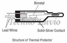
How It Works:
-
Temperature increases → bimetal strip bends
-
Electrical contact opens
-
Motor power is interrupted
Features:
-
Simple and reliable
-
Self-resetting or manual reset
-
Common in small motors
Typical Applications:
Fans, pumps, compressors, household and light industrial motors
2. PTC Thermistors (Positive Temperature Coefficient)
PTC sensors are widely used in industrial motors.
Operating Principle:
-
Resistance increases sharply at a specific temperature
-
Connected to a thermal relay or PLC input
-
Triggers alarm or shutdown
Characteristics:
Advantages:
-
High accuracy
-
Fast response
-
Suitable for VFD-driven motors
3. RTDs (Resistance Temperature Detectors)
RTDs provide precise temperature measurement.
Common Types:
-
PT100
-
PT1000
Resistance Equation:
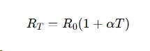
Where:
-
R0R_0 = Resistance at 0°C
-
α\alpha = Temperature coefficient
Applications:
-
Large motors
-
Critical processes
-
Predictive maintenance systems
4. Embedded Thermostats (Klixon Switches)
These are temperature-sensitive switches mounted directly on windings.
-
Normally closed (NC)
-
Open at preset temperature
-
Used for direct motor shutdown or alarm
Built-in Protection vs External Overload Relay
| Feature | Built-in Thermal Protection | External Overload Relay |
|---|---|---|
| Senses | Actual winding temperature | Motor current |
| Accuracy | High | Indirect |
| Response | Fast | Moderate |
| Reset | Auto or manual | Manual or auto |
| Cost | Higher | Lower |
Best practice: Use both together for maximum protection.
Integration with Motor Control Systems
Built-in thermal sensors can be connected to:
-
PLC digital or analog inputs
-
Motor protection relays
-
VFD thermal inputs
-
HMI alarm systems
This enables:
-
Early warning alarms
-
Controlled shutdown
-
Maintenance planning
NEC and IEC Considerations
Electrical standards often require:
-
Overload protection for motors
-
Proper labeling of thermal devices
-
Coordination between thermal protection and starters
Built-in thermal protection does not replace required external protection unless specifically approved.
Practical Industrial Motor Example
Application: VFD-Driven Conveyor Motor
Challenges:
-
Low-speed operation
-
Reduced cooling airflow
-
High thermal stress
Solution:
-
Motor with embedded PTC sensors
-
PTC relay linked to VFD trip input
-
Automatic shutdown before overheating
Common Mistakes to Avoid
-
Ignoring built-in thermal sensors during wiring
-
Assuming external overloads are sufficient
-
Bypassing thermal protection during troubleshooting
-
Using motors without thermal protection in critical applications
Conclusion
Correct motor installation ensures long-term reliability, safety, and efficiency. Key steps include solid foundations, precise mounting, proper alignment, electrical connections, grounding, correct conductor sizing, voltage monitoring, and thermal protection.
By combining practical installation tips, equations, and mini-project experiments, engineers and technicians can optimize motor performance and extend service life.