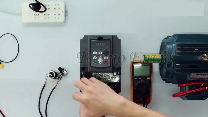
How to Connect an AC Inverter to an Electric Motor
Connecting an AC inverter (VFD) to an electric motor is a critical step that directly affects motor performance, efficiency, safety, and lifespan. Incorrect wiring or poor parameter setup can cause overheating, nuisance trips, torque loss, or even permanent damage to the inverter or motor.
This guide provides a step-by-step, practical explanation of how to correctly wire, configure, and test an AC inverter with an electric motor. It also covers control wiring, communication signals, advanced setup parameters, real equations, and hands-on project examples, making it suitable for beginners and technicians alike.
1. Pre-Installation Checks (Do Not Skip)
Before touching any wires, verify the following:
1.1 Match Inverter and Motor Ratings
Always compare the motor nameplate with the inverter specifications.
Check:
-
Motor voltage (V)
-
Motor current (A)
-
Motor frequency (Hz)
-
Motor power (kW or HP)
-
Motor speed (RPM)
Rule:
The inverter current rating must be greater than or equal to the motor rated current.
Example:
If motor rated current = 8.2 A, inverter output current should be ≥ 8.2 A (preferably with margin).
1.2 Power Supply Compatibility
Verify:
-
Single-phase or three-phase input
-
Input voltage range (e.g., 220–240 V or 380–415 V)
-
Proper grounding system
⚠️ Never connect a three-phase inverter to a single-phase motor unless explicitly supported.
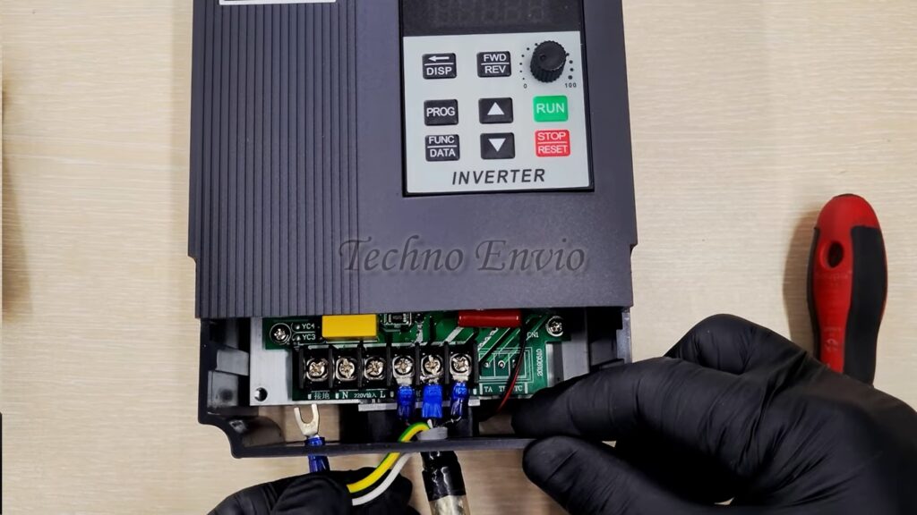
2. Power Wiring: Inverter to Motor
2.1 Main Power Terminals
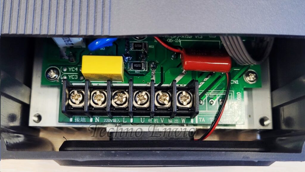
Most AC inverters have the following terminals:
| Terminal | Description |
|---|---|
| R / L1 | Input phase |
| S / L2 | Input phase |
| T / L3 | Input phase |
| U | Motor output |
| V | Motor output |
| W | Motor output |
| PE / ⏚ | Ground |
2.2 Input Power Wiring
Connect the mains supply to the inverter input terminals:
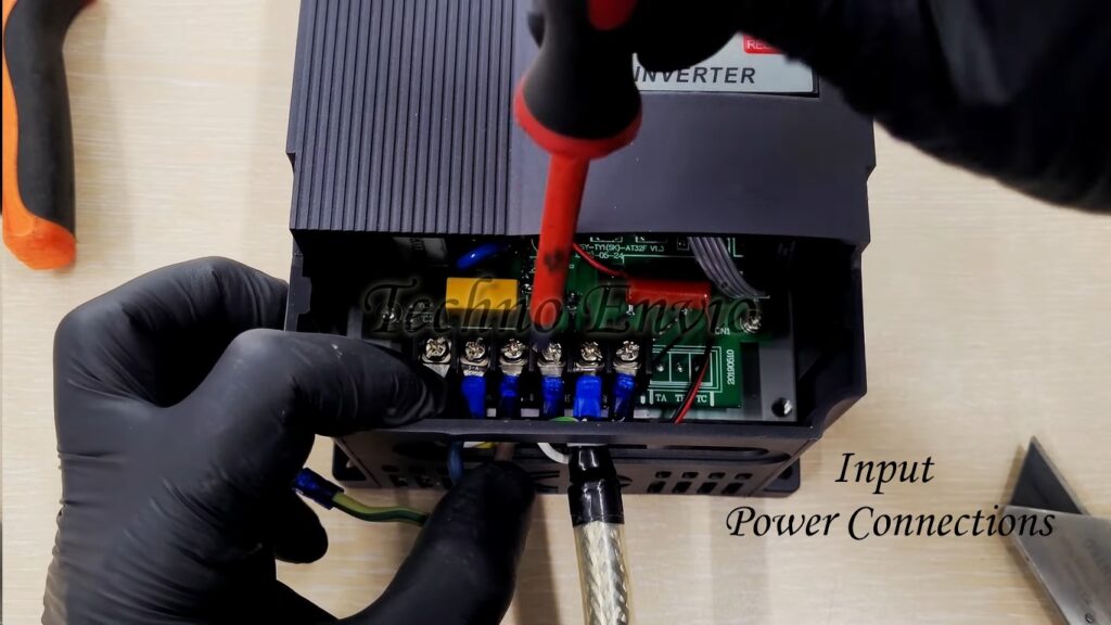
-
Single-phase: L → R/L1, N → S/L2
-
Three-phase: R → L1, S → L2, T → L3
Always install:
-
MCCB or MCB
-
Contactor (optional)
-
Input fuse (recommended)
2.3 Motor Output Wiring
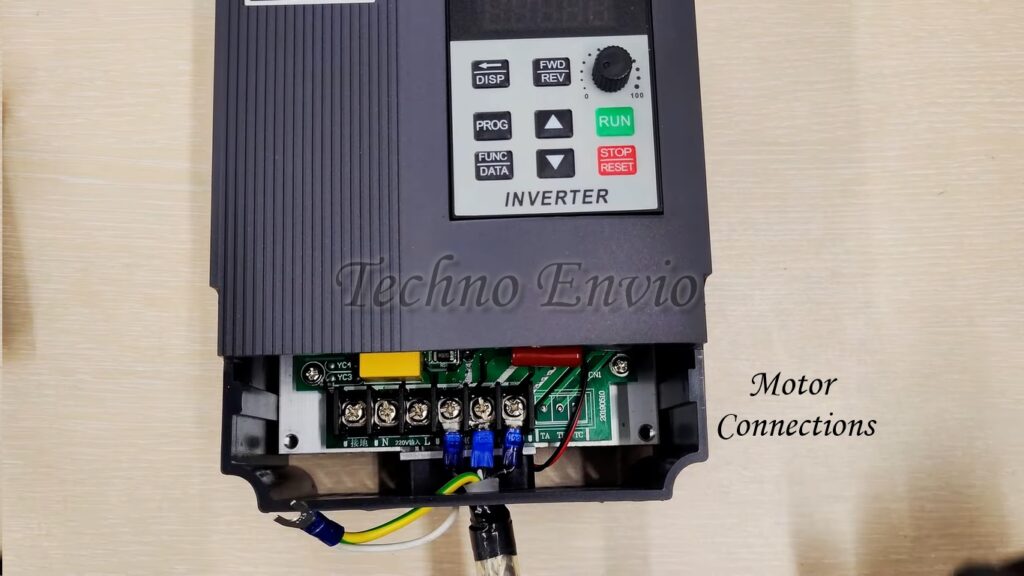
Connect the motor directly to:
-
U → Motor terminal 1
-
V → Motor terminal 2
-
W → Motor terminal 3
⚠️ Do NOT place a contactor between inverter and motor while the inverter is running.
2.4 Grounding (Very Important)
-
Ground inverter body to earth
-
Ground motor frame to earth
-
Use short, thick ground cables
Proper grounding:
-
Reduces electrical noise
-
Prevents inverter faults
-
Protects personnel
3. Motor Terminal Connection (Star / Delta)
Motor terminal configuration depends on voltage.
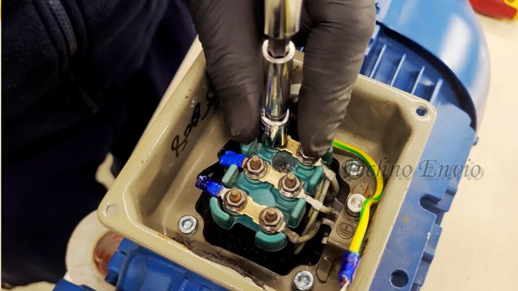
Example Motor Nameplate:
-
If inverter output = 230 V → Delta (Δ)
-
If inverter output = 400 V → Star (Y)
Incorrect connection will cause:
-
Overcurrent
-
Low torque
-
Motor overheating
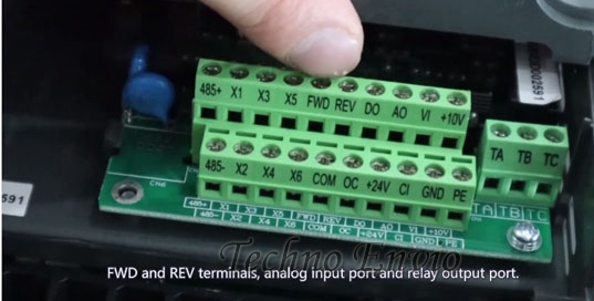
4. Control Wiring Basics
Control wiring allows you to start, stop, change speed, and direction without using the keypad.
4.1 Digital Inputs (DI)
Typical terminals:
-
DI1: Start
-
DI2: Stop
-
DI3: Forward / Reverse
-
COM: Common
Example:
-
Push button between DI1 and COM → Start motor
4.2 Analog Speed Control (0–10V / 4–20mA)
Most inverters support analog speed reference.
Terminals:
-
AI: Analog input
-
+10V: Reference supply
-
GND / COM
Potentiometer Wiring (10kΩ):
-
One end → +10V
-
Middle → AI
-
Other end → GND
Speed equation:
Example:
-
AI = 5 V
-
Max frequency = 50 Hz
-
Output = 25 Hz
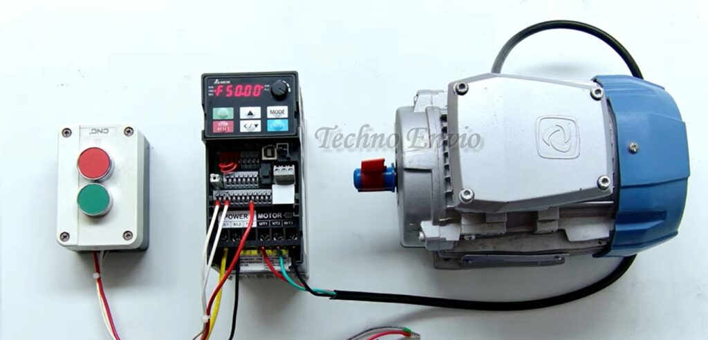
5. AC Inverter Control Wiring
5.1. Buttons Control + Speed Control by Inverter Keypad
Application
-
Training panels
-
Commissioning and testing
-
Simple machines
Wiring Concept
-
Start / Stop via external buttons
-
Speed reference from inverter keypad
Control Wiring
-
Start button → DI1 to COM
-
Stop button → DI2 to COM
Parameter Settings
-
Command source = Terminal (DI)
-
Speed reference = Keypad
-
Forward/Reverse = Optional DI or keypad
Operation Logic
-
Operator presses Start button
-
Inverter runs
-
Speed is adjusted using ▲ / ▼ keys on keypad
Advantages
-
Very simple
-
No analog wiring
-
Good for beginners
Limitations
-
Operator must access inverter keypad
-
Not suitable for remote control
5.2. Buttons Control + Speed Control by Internal Potentiometer (Keypad Pot)
Application
-
Small machines
-
Local manual speed adjustment
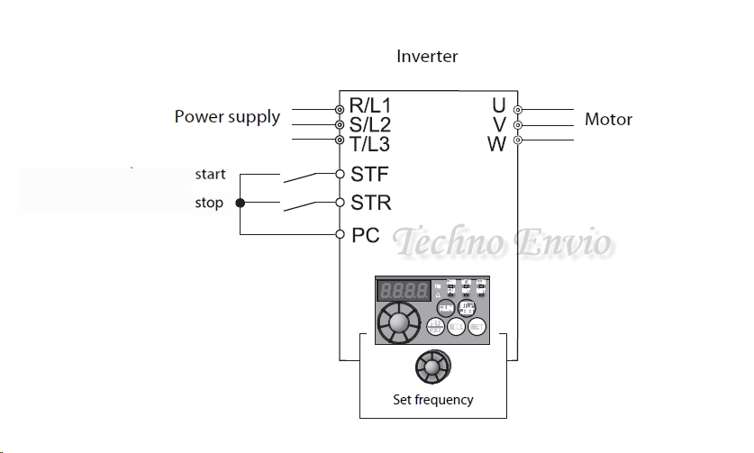
Wiring Concept
-
Start/ Stop→ External buttons
-
Speed → Built-in inverter potentiometer
Control Wiring
-
Start→ STF
-
Stop→ STR
-
PC→ Common
(No analog wiring required)
Parameter Settings
-
Run command = Terminal
-
Speed source = Internal potentiometer
Operation Logic
-
Press Start button
-
Rotate inverter knob to increase/decrease speed
Advantages
-
No extra components
-
Fast setup
Limitations
-
Manual control only
-
Limited precision
5.3. Buttons Control + Speed Control by External Potentiometer
Application
-
Conveyors
-
Mixers
-
Packaging machines
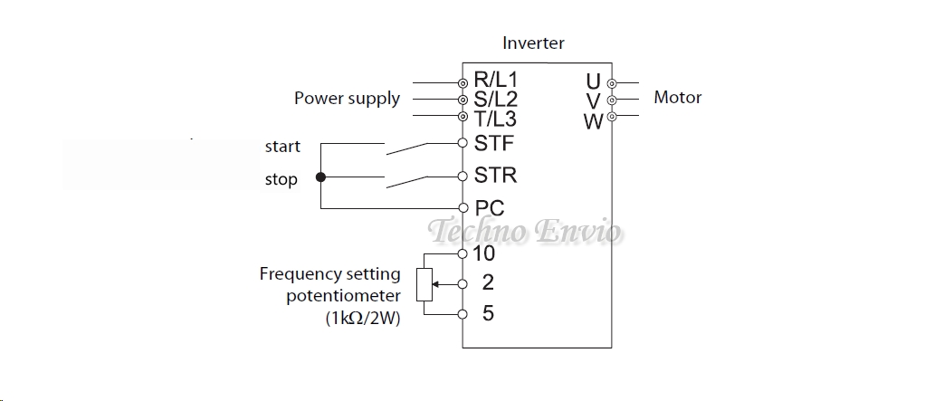
Wiring Concept
-
Start / Stop → Push buttons
-
Speed → External 10kΩ potentiometer
Wiring Diagram Logic
-
Pot terminal 1 → +10V
-
Pot terminal 2 (wiper) → AI
-
Pot terminal 3 → GND
Control Wiring
-
Start → DI1
-
Stop → DI2
-
COM → Common
Parameter Settings
-
Command source = Terminal
-
Speed reference = Analog input (0–10 V)
-
Max frequency = 50 or 60 Hz
Speed Equation

Advantages
-
Remote speed control
-
Smooth adjustment
Limitations
-
Analog noise possible
-
Cable shielding required for long distances
5.4. Buttons Control + Speed Control by Multi-Speed (Preset Frequencies)
Application
-
Sorting conveyors
-
Indexing tables
-
Machines with fixed speeds
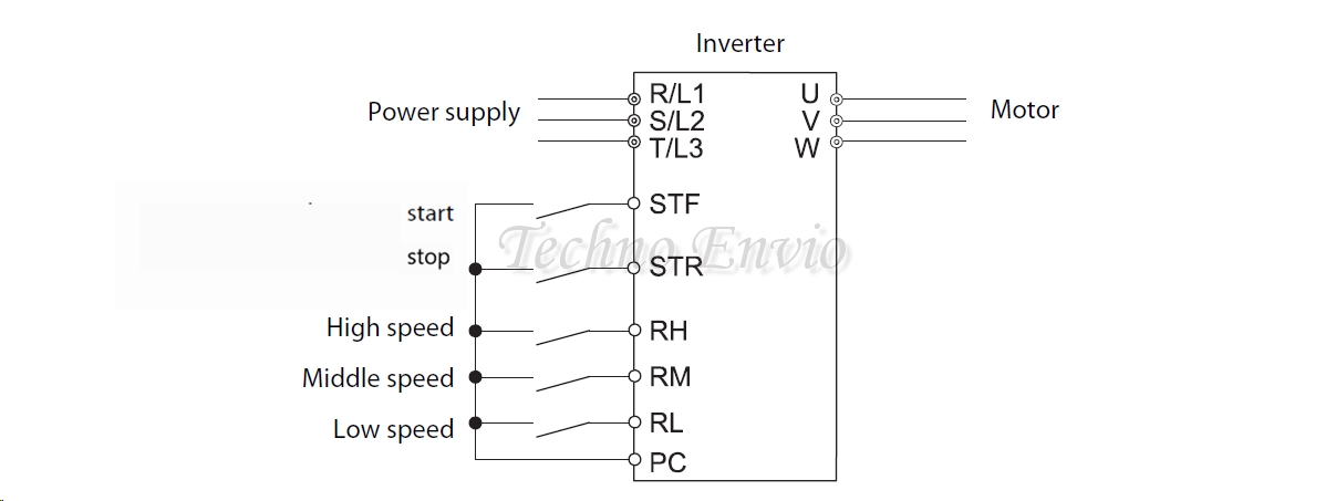
Wiring Concept
-
Start / Stop → Push buttons
-
Speed → Multiple digital inputs
Example Wiring
| Input | Function |
|---|---|
| DI1 | Start |
| DI2 | Stop |
| DI3 | Speed 1 |
| DI4 | Speed 2 |
| DI5 | Speed 3 |
Parameter Settings
-
Speed mode = Multi-step / Preset speed
-
Preset frequency 1 = 15 Hz
-
Preset frequency 2 = 30 Hz
-
Preset frequency 3 = 50 Hz
Logic Table Example
| DI3 | DI4 | Speed |
|---|---|---|
| 0 | 0 | Speed 1 |
| 1 | 0 | Speed 2 |
| 0 | 1 | Speed 3 |
Advantages
-
No analog signals
-
High repeatability
-
Immune to noise
Limitations
-
Fixed speeds only
-
Requires more digital inputs
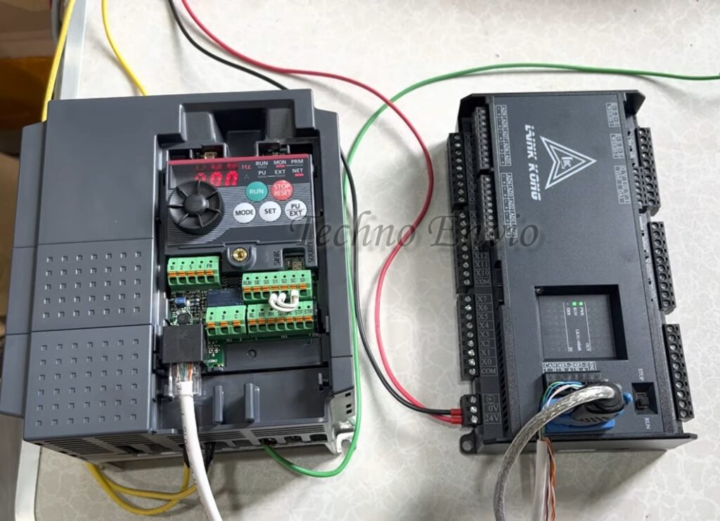
5.5. Buttons Control + Speed Control by Modbus Communication
Application
-
PLC-controlled systems
-
SCADA integration
-
Centralized control panels
Wiring Concept
-
Start / Stop → Push buttons (backup/manual)
-
Speed → PLC via Modbus
Communication Wiring
-
RS-485 D+ → Inverter D+
-
RS-485 D− → Inverter D−
-
Shield grounded at one end
Parameter Settings
-
Command source = Communication
-
Speed reference = Communication
-
Modbus address = Unique
-
Baud rate = 9600 / 19200
Data Flow
-
PLC writes frequency command
-
PLC reads inverter status & faults
Advantages
-
Full automation
-
Remote monitoring
-
Scalable system
Limitations
-
Requires PLC programming
-
Communication configuration needed
5.6. Buttons Control + Speed Control by Profibus Communication
Application
-
Siemens PLC systems
-
Large industrial plants
-
High-speed deterministic control
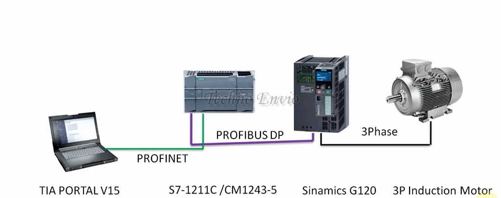
Wiring Concept
-
Start / Stop → Hardwired buttons (safety/manual)
-
Speed → PLC via Profibus
Profibus Wiring
-
Shielded Profibus cable
-
Termination resistors at both ends
-
Proper grounding
Parameter Settings
-
Control mode = Fieldbus
-
Speed reference = Profibus
-
GSD file installed in PLC
Data Exchanged
-
Control word (Start/Stop/Reset)
-
Speed setpoint
-
Status word
-
Fault codes
Advantages
-
High reliability
-
Fast communication
-
Industry standard
Limitations
-
Higher cost
-
More complex setup
5.7. Hybrid Control (Buttons + Communication Backup)
Typical Use Case
-
Normal operation via PLC
-
Emergency or manual mode via buttons
Logic
-
Selector switch chooses control mode
-
DI enables terminal or communication
Benefits
-
Redundancy
-
Maintenance-friendly
-
Safer operation
5.8. Comparison Table of Control Methods
| Method | Wiring | Accuracy | Noise Immunity | Typical Use |
|---|---|---|---|---|
| Keypad | Very Low | Medium | High | Testing |
| Internal Pot | Low | Medium | High | Small machines |
| External Pot | Medium | High | Medium | Conveyors |
| Multi-Speed | Medium | Very High | Very High | Fixed speeds |
| Modbus | Medium | Very High | High | Automation |
| Profibus | High | Very High | Very High | Industrial plants |
5.9. Practical Recommendation
-
Training / Testing → Keypad or internal pot
-
Manual machines → External potentiometer
-
Repeatable speeds → Multi-speed
-
Automation systems → Modbus
-
Siemens environments → Profibus
6. Basic Motor Parameters (Must Be Set)
After wiring, program these mandatory parameters.
6.1 Motor Rated Voltage
Set according to motor nameplate.
Example:
6.2 Motor Rated Current
Used for overload protection.
Example:
6.3 Motor Rated Frequency
Usually:
-
50 Hz
-
60 Hz
6.4 Motor Rated Speed or Poles
Used for slip compensation and torque control.
Equation:
Example:
-
50 Hz
-
4 poles
7. Acceleration and Deceleration Setup
7.1 Acceleration Time
Time to reach target speed.
Too short → Overcurrent fault
Too long → Slow response
Example:
7.2 Deceleration Time
Time to stop motor.
If too short:
-
DC bus overvoltage
-
Need braking resistor
8. Advanced Motor Control Parameters
8.1 V/f Curve Adjustment
Used to optimize torque.
-
Linear V/f → Standard loads
-
Quadratic V/f → Fans and pumps
-
Custom V/f → Heavy starting loads
8.2 Torque Boost
Increases voltage at low frequency.
Useful for:
-
Conveyors
-
Crushers
-
Mixers
Example:
Too high → Motor overheating
8.3 Slip Compensation
Maintains speed under load.
Equation:
Higher slip compensation improves torque but increases current.
9. Direction Control and Interlocks
Forward / Reverse is controlled by:
-
Digital input
-
Keypad
-
Communication command
⚠️ Always stop motor before reversing direction.
10. Communication Between Inverter and Control Systems
10.1 Common Communication Protocols
-
Modbus RTU (RS-485)
-
Modbus TCP
-
Profibus
-
CANopen
-
Ethernet/IP
10.2 RS-485 Wiring (Modbus RTU)
Terminals:
-
D+ (A)
-
D− (B)
-
GND (optional)
Rules:
-
Use twisted pair cable
-
Shielded cable preferred
-
Termination resistor (120Ω) at last device
10.3 Communication Parameters
Set:
-
Slave address
-
Baud rate (e.g., 9600 / 19200)
-
Parity
-
Stop bits
Example:
10.4 Data Exchanged via Communication
You can:
-
Start / stop motor
-
Set frequency
-
Read current, voltage, faults
-
Monitor temperature
11. Protection and Safety Settings
11.1 Overload Protection
Set motor thermal protection:
11.2 Overvoltage and Undervoltage
Protects inverter during:
-
Regeneration
-
Supply fluctuation
11.3 Stall Protection
Stops motor if:
-
Speed = 0
-
Current is high
Useful for jammed machines.
12. Testing and Commissioning Procedure
Step-by-Step Test
-
Disconnect motor
-
Power inverter
-
Check no fault
-
Connect motor
-
Run at 5–10 Hz
-
Check rotation direction
-
Increase speed gradually
-
Monitor current and temperature
13. Practical Mini Project
Project: Conveyor Belt with Speed Control
Components:
-
1.5 kW motor
-
AC inverter
-
Potentiometer
-
Start/Stop push buttons
Steps:
-
Wire motor to U-V-W
-
Wire pot to analog input
-
Set motor parameters
-
Acceleration = 15 sec
-
Max frequency = 50 Hz
Result:
-
Smooth start
-
Adjustable speed
-
Energy efficient operation
14. Common Wiring Mistakes to Avoid
-
Switching motor output while inverter is running
-
Incorrect motor star/delta connection
-
Poor grounding
-
Using contactor on inverter output
-
Incorrect motor current setting
15. Best Practices for Reliable Operation
-
Always follow motor nameplate
-
Keep control and power cables separate
-
Use shielded cables
-
Save inverter parameters after setup
-
Perform regular inspections
Conclusion
Correctly connecting an AC inverter to an electric motor requires more than just wiring three cables. Proper setup involves accurate parameter configuration, control wiring, communication integration, and protection settings. When done correctly, the system delivers smooth operation, precise speed control, lower energy consumption, and extended equipment life.
This guide provides a complete, practical foundation you can confidently apply to real industrial projects or educational setups.