Timer delay relays are broadly classified into two types: on-delay relays and off-delay relays.
DOE, which stands for “Delay On Energize,” is another name for the on-delay relay. DODE, which stands for “Delay On De-Energize,” is another name for the off-delay relay.
Timer relays, like other control relays, employ a coil to regulate the functioning of a number of contacts. The distinction between a control relay and a timer relay is that the timer relay’s contacts change position once the coil is energized or de-powered. When electricity is applied to the coil of an on-delay timer, the contacts delay changing position for a predetermined amount of time. Assume that the timer has been set to a delay of 10 seconds for this example.
Timer
contacts of Timer
Assume the contact is ordinarily open as well.
When a voltage is applied to the coil of the on-delay timer, the contacts will remain open for 10 seconds before closing. When the electricity is released and the coil is de-energized, the contact returns to its typically open state quickly. Figure 3-1 depicts the contact symbols for an on-delay relay.
Figure 3-1 shows On-delay typically open and normally closed contacts.
The off-delay timer operates in the opposite manner as the on-delay timer. Assume, once again, that the timer has been set for a delay of 10 seconds and that the contact is ordinarily open. When a voltage is provided to the coil of the off-delay timer, the contact changes from open to closed instantly. When the coil is de-energized, however, the contact remains closed for 10 seconds before reopening. Figure 3-2 depicts the contact symbols for an off-delay relay. Time-delay relays might have contacts that are generally open, normally closed, or a mix of the two.
Figure 3-2 shows Off-delay typically open and normally closed contacts.
Although the contact symbols in Figures 3-1 and 3-2 are NEMA standard for on-delay and off-delay contacts, certain control schematics may utilize a different manner of denoting timed connections. Some control diagrams use the initials TO and TC to denote a time-operated contact. TO is an abbreviation for time opening, whereas TC is an abbreviation for time closing. When these abbreviations are used with regular contact symbols, the meaning might get muddled.
Figure 3-3 depicts a conventional typically open contact sign with the acronym TC written beneath it.
Figure 3–3 Time closing contact.
If this contact is to be time delayed while closing, it must be linked to an on-delay relay. The identical interaction is shown in Figure 3-4, but with the abbreviation TO beneath it. If this contact is to be time delayed upon opening, an off-delay timer must be used.
Figure 3–4 Time opening contact.
As demonstrated in Figure 3-5, these abbreviations can also be utilized with regular NEMA symbols.
Figure 3–5 Contact A has the acronym NOTC for an on-delay contact (normally open time closing).
Contact B is an off-delay contact denoted by the acronym NOTO (normally open time opening).
Pneumatic Timer
Pneumatic timers work by limiting the flow of air through an opening to a rubber bellows or diaphragm.
The operation of a basic bellows timer is seen in Figure 3-6. As the bellows compresses, air is forced out via the check valve if rod “A” is pushed against the end of the bellows.
When the bellows is retracted, contact TR shifts from open to closed. The spring attempts to restore the bellows to its original position when rod “A” is pushed away from the bellows. However, before the bellows can be restored to their original position, air must enter the bellows via the air input port.
Figure 3–6: Pneumatic timer with bellows.
The needle valve regulates the pace at which air is allowed to enter the bellows. Contact TR returns to its typically open state when the bellows returns to its original position.
Pneumatic timers are widely used in industry because they offer the following advantages:
A. They are not impacted by changes in temperature or air pressure.
B. They can be set for a variety of time periods.
C. They have high repeatability.
D. They are offered with a choice of contact and scheduling options.
Some pneumatic timers are intended to allow the timer to be switched from on-delay to off-delay, as well as the contact arrangement to be switched from normally open to normally closed (Figure 3–7). Another reason for pneumatic timers’ appeal is their adaptability.
Figure 3–7 shows Pneumatic timer.
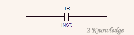
Many timers are built with coil-operated contacts as well as time-delayed contacts. When these contacts are employed, they are referred to as instantaneous contacts, and the term INST. is displayed below the contact on a schematic diagram (Figure 3–8). When the coil is activated, these instantaneous contacts change positions quickly and return to their usual locations as soon as the coil is de-powered.
Figure 3–8 shows A timer relay’s normally open instantaneous contact.
Clock Timers
The clock timer (Figure 7-9) is another common timer. To give the time measurement for the timer, clock timers employ a tiny AC synchronous motor similar to the motor found in a wall clock. The length of time of one clock timer may differ substantially from that of another. For example, one timer may have a whole range of 0 to 5 seconds and another timer may have a range of 1 to 5 seconds.
Figure 3–9 shows Clock Timer.
offer a complete range of 0 to 5 hours. Both timers might utilize the same sort of timer motor. The ratio of gears
The timer’s entire range of time would be determined by connecting it to the motor. The following are some of the benefits of clock timers:
A. They have a high repetition accuracy.
B. The modification of the time setting is straightforward and quick. Clock timers are typically utilised when the machine operator has to modify the time length.
Motor-Driven Timers
A motor-driven timer is often employed when a process has a distinct on and off activity or a sequence of subsequent activities (Figure 3–10).
A motor-driven timer is commonly used to manage laundry washers, where the loaded motor is run in one way for a certain amount of time, reversed, and then run in the opposite direction.
A tiny, synchronous motor drives a cam-dial assembly on a shared shaft in this sort of timer. A motor-driven timer shuts and opens switch contacts that are wired in circuits to engage control relays or contactors to perform desired activities.
Figure 3-10 Process timer powered by a motor. A cam timer is another name for it.
Typical specifications.
Min. Time Delay: 0.05 second
Max. Time Delay: 3 minutes
Minimum Reset Time: 0.75 second
Accuracy: 610 percent of setting
Contact Ratings:
AC
6.0 A, 115 V
3.0 A, 230 V
1.5 A, 460 V
1.2 A, 550 V
DC
1.0 A, 115 V
0.25 A, 230 V
Coils can be supplied for voltages and frequencies of up to 600 volts, 60 hertz AC, and 250 volts DC.
Contact Types: One generally open and one normally closed. Contacts made of cadmium silver alloy.
Capacitor Time Limit Relay
Assume a capacitor is charged by briefly connecting it across a DC line, and then the capacitor direct current is discharged via a relay coil. Depending on the relative quantities of capacitance, inductance, and resistance in the discharge circuit, the current produced in the coil will diminish slowly.
When a relay coil and a capacitor are connected in parallel to a DC line (Figure 3-11), the capacitor charges to the line voltage and a current flows through the coil.
Figure 3-11 A charged capacitor discharges through a relay coil.
The graph on the right depicts the coil’s current drop.
If the coil and capacitor combination is now disconnected from the line, the current in the coil will begin to fall following the curve indicated in Figure 3-11.
A time delay of t1 is produced by adjusting the relay so that the armature is released at current i1. The time delay may be prolonged to t 2 by setting the relay so that the armature does not release until the current is lowered to I 2. Figure 3-12 depicts a relay used for time management.
To change the time, a potentiometer is utilized as an adjustable resistor. Resistance-capacitance (RC) theory is also applied in industrial electronics and solid-state controllers. This timer is extremely precise and is utilized in motor acceleration control as well as a variety of industrial procedures.
Figure 3-12 Limit controller for capacitor timers.
(This is commonly utilized with direct current control systems.)
Electronic Timers
Electronic timers give the necessary time delay by utilizing solid-state components. Some of these timers employ an RC time constant as the time foundation, while others use quartz clocks (Figure 3–13). RC time constants are cheap and have a long repetition time.
Figure 3-13 Digital clock timer
Quartz timers, on the other hand, are incredibly precise and may frequently be adjusted for 0.1 second intervals. These timers are often contained in a plastic casing and are intended to be plugged into a socket. Figure 3-14 depicts an electronic timer designed to be inserted into a normal eight-pin tube socket. The time delay may be adjusted by twisting the control knob visible on top of the timer.
Figure 3-14 Electronic timer
Eight-pin electron timers like the one illustrated in Figure 3-15 are solely suitable for use as on-delay timers. Many electronic timers are more versatile because they plug into an eleven-pin tube socket (Figure 7-16).
Figure 3–15 shows 11-pin tube sockets.
Figures 3-16A and 3-16B illustrate two examples of such timers. These timers can be used as on-delay timers, off-delay timers, pulse timers, or one-shot timers.
Figure 3–16A Dayton electronic timer.
Figure 3–16B shows Allen-Bradley electronic timer.
Pulse timers cycle on and off at regular intervals. Figure 7-18 depicts a timing period chart for a pulse timer with a delay of one second. A one-shot timer will only run for one second.
Figure 3–17 shows a timing chart for a pulse timer.
Figure 7-19 is a timing period chart for a one-shot timer set to 2 seconds.
Figure 3–18 shows the timing chart for a one shot timer.
Most electronic timers provide a broad range of time settings. The timer depicted in Figure 3-16A is controlled by a thumbwheel switch. The top selection switch may be used to specify a value ranging from 9.99 seconds to 999 minutes. The timer’s range is 0.01 second to 999 minutes (16 hrs. 39 min.).
By modifying the range and units settings on the front of the timer, the timer depicted in Figure 3-16B may be configured for a range of 0.01 second to 100 hours. Most electrical timers have similar functions.
Connecting 11-Pin Timers
In general, putting eleven-pin timers into a circuit is a little more complicated than just connecting the coil to power. Before attempting to connect one of these timers, please review the manufacturer’s instructions. Although most electronic timers are linked in the same way, there are some variances.
Figure 3-19 depicts the pin connection schematic for the timer depicted in Figure 3-16A. A typically open push-button switch is illustrated between terminals 5 and 6. When the timer is set to function as an off-delay timer or a one-shot timer, this switch is used to initiate the timer’s operation.
Figure 3–19 Shows Pin connection diagram for Dayton timer.
This is because, in order for the timer to work as an off-delay timer, power must be given to the timer at all times in order for the internal timing circuit to operate. The inbuilt timer cannot work if power is withdrawn. When the timer is programmed to operate in the off-delay mode, the start switch is used to start the timer. Remember how an off-delay timer works:
When the coil is turned on, the contacts instantaneously shift positions. When the coil is de-energized, the contacts take longer to restore to their original position. Pins 2 and 10 are connected to the timer’s coil, according to the pin chart illustrated in Figure 3-19. Power must be connected to pins 2 and 10 at all times while using this timer in off-delay mode. When pins 5 and 6 are shorted together, the timed contacts immediately change position. The time sequence begins when the short circuit between pins 5 and 6 is broken.
The contacts will revert to their usual position after the timer expires.
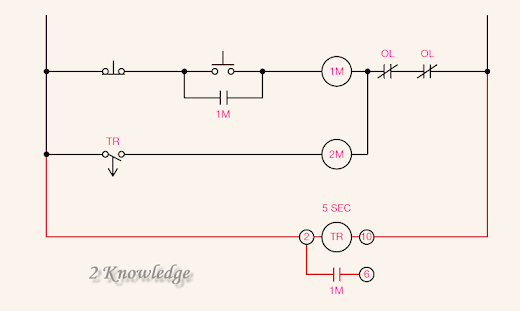
If electronic off-delay timers are to replace pneumatic off-delay timers in a control circuit, the circuit must typically be modified. In Figure 3-20, for example, it is assumed that starters1Mand2Mcontrol the functioning of two motors, and timer TR is a pneumatic off-delay timer. When you hit the start button, two motors start at the same time. The motors will continue to run until the stop button is hit, at which point motor #1 will stop immediately. Motor #2, on the other hand, will continue to run for 5 seconds before halting.
Figure 3-20 Shows A pneumatic timer is used in an off-delay timer circuit.
Consider replacing the pneumatic off-delay timer with an electronic off-delay timer (Figure 3-21). Notice how the timer’s coil is linked directly across the incoming power in this circuit, allowing it to remain activated at all times. The timer really runs with starter 1M in the circuit depicted in Figure 3-20. When coil 1M turns on, timer TR turns on as well. When coil 1M de-energizes, so does timer TR. As a result, the functioning of the electronic off-delay timer will be controlled by a typically open auxiliary contact on starter 1M.
Figure 3–21 Shows Modifying the circuit for an electronic off-delay timer.
A pair of typically open 1M contacts are connected to the timer’s pins 5 and 6 in the circuit seen in Figure 3-21. Contact 1M closes and shorts pins 5 and 6 when coil 1M energizes, which causes the usually open TR contacts to shut and energize starting coil 2M. The connections reopen and timer TR starts timing when coil 1M is de-energized. Contacts TR reopen and de-energize starting coil 2M after 5 seconds.
Although there are some variances in how they should be linked, all electronic clocks have several characteristics.
Figure 3-22 displays the connection diagram for the timer seen in Figure 7-17B. Take note of the RESET, START, and GATE pins on this timer. When pins 2 and 5 are connected, the GATE function is activated, which stops or suspends the internal clock’s activity. The START function, which functions like the timer in Figure 3-16A, is activated by connecting pin 2 to pin 6. The internal clock is reset to zero when the RESET function is activated by connecting pins 2 and 5.
If this timer is to be used in the circuit seen in Figure 3-21, it must be adjusted as depicted in Figure 3-23 by connecting the 1M usually open contact to pins 2 and 6 rather than pins 5 and 6.
Figure 3–22 Shows Allen-Bradley timer pin connection
Figure 3–23 Shows Using the Allen-Bradley timer instead of the Dayton timer.
Construction of a Simple Electronic Timer
Figure 7-25 depicts the schematic for a basic on-delay timer. The timer works like this: When switch S1 is closed, electricity passes via resistor RT, starting the charging process for capacitor C1. When capacitor C1 is charged to the unijunction transistor’s trigger value, the UJT switches on and discharges capacitor C1 to ground through resistor R2. A spike voltage appears across resistor R2 due to the abrupt discharge of capacitor C1. This voltage spike passes through capacitor C2 and activates the silicon-controlled rectifier’s gate (SCR). When the SCR is activated, electricity is sent to the coil of relay K1.
Figure 3-24 Shows Electronic on-delay timer schematic.
The current flow through the UJT is limited by resistor R1. Resistor R3 is utilized to keep the SCR switched off until the gate is activated by the UJT. When the current is shut off, diode D1 protects the circuit from the spike voltage created by the collapsing magnetic field surrounding coil K1.
Capacitor C1 may be charged at varying rates by altering resistor RT. The relay can be modified for time in this manner. The SCR will stay switched on until switch S1 is turned off.
Programmable controllers, which will be covered in next post, have “internal” electronic timers. The time foundation for the majority of programmable controllers (PLCs) is a quartz-operated clock. When the controller is configured, the timers may be set in 0.1 second increments. This, of course, gives the controller with highly precise time delays.