A proximity sensor is a device that detects or senses the approach or presence of adjacent objects without requiring physical touch.
Types of Proximity Sensor
Inductive Proximity Sensor
Applications
Metal detectors are essentially proximity detectors. They are used to detect the presence or absence of metal without the need for physical contact. This reduces wear on the detector and allows it to identify red hot metals. Most proximity detectors are solely intended to detect ferrous metals, although other systems can detect all metals.
Circuit Operation
There are various approaches for creating proximity detectors.
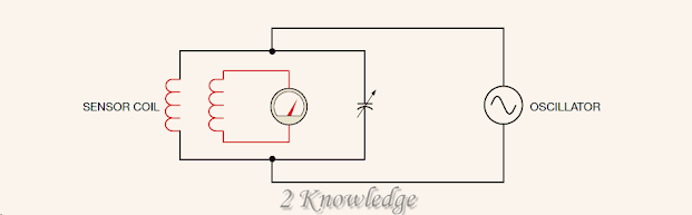
Figure 4-1 depicts one way. This is a very simple circuit designed to demonstrate the working of a proximity detector. A series resistor connects the sensor coil to an oscillator. In this example, a voltage detector, a voltmeter, is connected across the resistor. Because this circuit receives an alternating current voltage, the quantity of current flow is governed by the resistance of the resistor and the inductive reactance of the coil. The voltage drop across the resistor is proportional to its resistance and the current flowing through it.
Figure 4–1 Shows Simple proximity detector.
When ferrous metal is placed near the sensor coil, its inductance rises. This results in an increase in inductive reactance and a decrease in current flow across the circuit. When the current flow through the resistor is reduced, so is the voltage drop across the resistor (Figure 4–2). The voltage drop can be utilized to switch relays or other devices on and off.
Figure 4-2 Shows The presence of metal causes
the voltage drop across the resistor to decrease.
This method of identifying metal does not work in all circumstances. Figure 4-3 depicts another approach that is more sensitive to tiny levels of metal. A tank circuit tuned to the frequency of the oscillator is used in this detector. Instead of one coil, the sensor head has two. A tiny transformer serves as this sort of sensor. Current flow around the tank loop is strong when the tank circuit is tuned to the frequency of the oscillator. This induces a strong voltage into the secondary coil of the sensor head.
Figure 4–3 Shows Tuned tank circuit used to detect metal.
The inductance of the coil rises when ferrous metal is put near the sensor, as seen in Figure 4-4.
When the coil’s inductance changes, the tank circuit no longer resonates with the frequency of the oscillator. This drastically reduces the current flow around the loop. As the current flow through the sensor coil decreases, so does the secondary voltage.
Figure 4–4 Shows The presence of metal detunes the tank circuit.
It is important to note that both sorts of circuits rely on a ferrous metal to adjust the inductance of a coil. If a detector is to detect nonferrous metals, a method other than modifying the coil’s inductance must be utilized. Figure 4-5 depicts the tank circuit used by an all-metal detector. All-metal detectors work at radio frequencies, and the tank circuit balance is utilized to keep the oscillator functioning. When the tank circuit becomes imbalanced, the oscillator shuts off. Eddy currents are induced into the surface of a nonferrous metal, such as aluminum, copper, or brass, when it is put near the sensor coil. Eddy currents in the metal cause the tank circuit to become imbalanced and the oscillator to stop working.
When the oscillator shuts down, another component of the circuit signals an output to switch on or off.
All-metal proximity detectors detect ferrous metals better than nonferrous metals.
A ferrous metal may be detected from approximately three times the distance of a nonferrous metal.
Figure 4–5 Shows Balance of the tank circuit permits the oscillator to operate.
Mounting
Some proximity detectors are manufactured as a single piece.
Other detectors make use of a control unit that may be put in a relay cabinet and a sensor located in a distant location. Figure 4-6 depicts many types of proximity detectors. Regardless of the type of detector utilized, installation the sensor should be done with care and planning. The sensor should be close enough to the target metal to generate a strong positive signal, but not so close that the sensor is struck by the metal item. One benefit of the proximity detector is that no physical contact between the detector and the metal item is required for the detector to detect the object.
Figure 4–6 Shows Proximity detectors.
Sensors should be installed as far from other metals as practicable. This is especially true for sensors used with metal detectors of various sorts.
In some circumstances, the sensor unit may need to be mounted on a nonmetal surface such as wood or plastic. If proximity detectors are to be used in regions with metal shavings or metal dust, care should be taken to position the sensor so that the shavings or dust do not accumulate around it. In some setups, it may be required to remove metal shavings or dust away from the sensor on a regular basis.
Capacitive Proximity Sensor
Although proximity detectors are commonly associated with metal detectors, there are other varieties that detect the presence of things that do not contain any metal.
One form of these detectors is based on capacitance changes.
When an item comes into contact with one of these detectors, a change in capacitance causes the detector to activate. Figure 4-7 depicts several distinct types of capacitive proximity detectors.
Figure 4–7 Shows Capacitive proximity detectors.
Because capacitive proximity detectors do not require metal to function, they may detect almost any substance, including wood, glass, concrete, plastic, and sheet rock. They may even be used with a seeing glass to detect liquid levels. One downside of capacitive proximity detectors is their extremely short range. Most cannot detect items more than one inch (25 millimetres) distant. Because they do not need to make touch with an item to measure its position, capacitive proximity detectors are often employed to replace mechanical limit switches. Most may work at a variety of voltages ranging from 2 to 250 volts AC or 20 to 320 volts DC.
Ultrasound Proximity Detectors
The ultrasonic detector is another sort of proximity detector that does not require the presence of metal to function. Ultrasonic detectors work by producing a high-frequency sound pulse and then detecting the echo when it bounces off an object (Figure 4–8).
Figure 4-8 Shows Ultrasonic proximity detectors
work by sending out high-frequency sound waves.
These detectors may be used to calculate the distance to an object by measuring the duration between the pulse’s emission and the return of the echo. Many ultrasonic sensors produce an analogue voltage or current output, the value of which is dependent by the object’s distance.
Figure 4-9 Shows Positioning ultrasonic proximity detectors
sensors.
This capability enables them to be employed in applications where the location of an item must be determined (Figure 4–9). Figure 4-10 depicts an ultrasonic proximity detector.
Figure 4–10 Shows Ultrasonic proximity detector.
Photosensors
Applications
In today’s industry, photodetectors are frequently used. They can detect the presence or absence of practically any item. Because photodetectors do not need to make physical touch with the thing they detect, there is no mechanical arm to wear out. Many photodetectors can function at rates that mechanical contact switches cannot. They are employed in practically every field, and their popularity is growing.
Types of Sensors
Photovoltaic, photoemissive, and photoconductive devices are the three types of photo-operated devices.
Photovoltaic
Solar cells are another name for photovoltaic devices. They are typically constructed of silicon and can generate a voltage in the presence of light. The substance of a cell determines the amount of voltage it generates. In the presence of direct sunshine, a silicon solar cell generates 0.5 volts. Current will flow across the circuit if a full circuit is connected to the cell. The surface area of a solar cell determines the quantity of current generated. Assume one solar cell has a surface area of one square inch and another has a surface area of four square inches. When exposed to direct sunshine, both silicon cells will generate 0.5 volts. The larger cell, on the other hand, will produce four times the current of the smaller one.
The schematic symbol for a photovoltaic cell is shown in Figure 4-11. Except for the arrow pointing toward it, the sign is identical to that used to symbolize a single cell battery. The battery icon indicates that the gadget can generate electricity, and the arrow indicates that it must be exposed to light in order to do so.
Figure 4–11 Shows Schematic symbol for a photovoltaic cell.
Photovoltaic cells offer the benefit of being able to power electrical devices without the use of an external power source.
Because silicon solar cells only produce 0.5 volts, it is sometimes required to link many of them together to acquire sufficient voltage and current to run the desired equipment. Assume solar cells are to be utilized to power a DC relay coil that demands 3 volts at 250 milliamperes. Assume that the solar cells to be utilized can generate 0.5 volts at 150 milliamperes.
Six solar cells put in series yield 3 volts at 150 milliamperes (Figure 4–12).
Figure 4-12 Shows Solar cells connected in series-parallel
create 3 volts at 300 milliamperes.
The voltage provided by the connection is adequate to power the relay, but the current capacity is insufficient. As a result, six more solar cells must be linked in series.
This connection is then paralleled with the first, resulting in a circuit with a voltage rating of 3 volts and a current rating of 300 milliamperes, both of which are adequate to activate the relay coil.
Photoemissive Devices
When in the presence of light, photoemissive devices emit electrons. They include devices like as the phototransistor, photodiode, and photo-SCR.
Figure 4-13 depicts the schematic symbols for these devices. Electron emission is employed to switch on these solid-state components. Figure 4-14 depicts a phototransistor used to activate a relay coil. When the phototransistor is in darkness, the base junction emits no electrons and the transistor is switched off. When the phototransistor detects light, it switches on and allows electricity to flow via the relay coil.
Figure 4-13 Shows Phototransistor, photodiode, and photo-SCR schematic symbols.
A kickback, or freewheeling, diode is a diode that is linked in parallel to the relay coil. Its purpose is to prevent induced voltage spikes from arising if the current abruptly ceases to flow through the coil and the magnetic field collapses.
The relay coil in Figure 4-14 will turn on when the phototransistor is in the presence of light and off when the phototransistor is in the presence of darkness.
Some circuits may necessitate reversal.
Figure 4–14 Shows Phototransistor controls relay coil.
This is done by including a resistor and a junction transistor into the circuit (Figure 4–15). A common junction transistor is utilized in this circuit to regulate the current flow via the relay coil. The current flow via the junction transistor’s base is limited by resistor R1. When in darkness, the phototransistor has a very high resistance. This allows current to pass to the junction transistor’s base and turn it on.
When the phototransistor detects light, it switches on and links the junction transistor’s base to the negative side of the battery. This turns off the junction transistor. In the circuit, the phototransistor serves as a stealer transistor. A stealer transistor takes the base current of another transistor in order to keep it switched off.
Figure 4–15 Shows The relay turns on when the phototransistor is in darkness.
Some circuits may demand a greater gain than the phototransistor has under typical conditions.
Figure 4-16 shows how to do this by utilizing a phototransistor as the driver for a Darlington amplifier circuit. A Darlington amplifier circuit has a gain of more than 10,000.
Photodiodes and photo-SCRs are utilized in circuits comparable to phototransistor circuits. In the presence of light, the photodiode will allow current to flow through it. The photo-SCR operates in the same way as a standard junction SCR. The main difference is that when utilizing a photo-SCR, light is employed to trigger the gate.
Figure 4-16 Shows A Darlington Amplifier is driven by the phototransistor.
The main benefit of the photoemissive device is speed, regardless of the type of photoemissive device employed or the type of circuit in which it is used. It just takes a few microseconds for a photoemissive device to switch on or off. Turning on or off photovoltaic or photoconductive devices typically takes several milliseconds. In high-speed switching circuits, this makes the employment of photoemissive devices essential.
Photoconductive Devices
Photoconductive devices vary resistance depending on whether or not light is present. Cadmium supplied cells, or cad cells, are the most common photoconductive device. In direct sunshine, a cad cell has a resistance of around 50 ohms and several hundred thousand ohms in darkness. It is most commonly used as a light sensitive switch. Figure 4-17 depicts the schematic symbol for a cad cell. A typical cad cell is seen in Figure 4-18.
Figure 4–17 Shows Schematic symbol for a cad cell.
Figure 4–18 Shows Cad cell.
Figure 4-19 depicts a simple circuit of a cad cell controlling a relay. When the cad cell is in the dark, it has a high resistance. This stops the current required to switch on the relay from going through the circuit. When exposed to light, the cad cell’s resistance decreases. The current required to operate the relay may now pass through the circuit.
Figure 4–19 Shows Cad cell controls relay coil.
Although this circuit will function if the cad cell is large enough to withstand the current, it has several flaws:
1. There is no method to change the circuit’s sensitivity.
Photoelectric switches are often found in a variety of locations across a facility. The intensity of the surrounding light might vary from one place to the next. As a result, the ability to adapt the sensor for the quantity of light required to function it is required.
2. The circuit’s sense of operation cannot be modified. The circuit presented in Figure 4-19 allows the relay to switch on when the cad cell detects light. There may be circumstances in which it is desired to activate the relay when the cad cell is dark.
Figure 4-20 depicts a photodetector circuit with a cad cell sensor and an operational amplifier (op amp) control circuit. The circuit works like this: Resistor R1 and the cad cell create a voltage divider circuit that is linked to the amplifier’s inverting input. R2 acts as a potentiometer to set a positive voltage at the noninverting input. This control modifies the circuit’s sensitivity. The current to a light-emitting diode is limited by resistor R3 (LED). The LED is positioned on the exterior of the photodetector enclosure and is used to signal when the relay coil is activated. The junction transistor’s base current is limited by resistor R4.
Figure 4-20 Shows When the cad cell detects light, the relay coil is activated.
The junction transistor regulates the current required to activate the relay coil. Many operational amplifiers do not have adequate current rating to handle this level of current. D1 serves as a kickback diode.
Assume that Resistor R2 has been set to generate a 6 volt potential at the noninverting input. When exposed to light, the cad cell has a low resistance and a voltage less than 6 volts is delivered to the inverting input. Because the noninverting input is coupled to a larger positive voltage, the output is also high. When the op amp’s output is high, the LED and transistor switch on.
When a cad cell is exposed to darkness, its resistance rises. A voltage larger than 6 volts is provided to the inverting input when its resistance exceeds 4.7 kilohms. This causes the op amp’s output to go from high to low, so turning off the LED and transistor. In this circuit, the relay is turned on when the cad cell is in the presence of light and off when it is in the presence of darkness.
Figure 4-21 depicts a connection that will cause the circuit to reverse its behavior. The voltage divider circuit has been linked to the noninverting input, and the potentiometer has been hooked to the inverting input. Assume that a voltage of 6 volts has been established at the inverting input to understand how this circuit works.
Figure 4–21 Shows The relay is energized when the cad cell is in darkness.
When exposed to light, the cad cell has a low resistance and a voltage less than 6 volts is delivered to the noninverting input. Because the inverting input is coupled to a higher positive voltage, the output is low, and the LED and transistor are switched off.
When the cad cell is exposed to light, its resistance rises over 4.7 kilohms, and a voltage larger than 6 volts is delivered to the noninverting input. This causes the op amp’s output to transition to a high state, turning on the LED and transistor.
Take note of how this circuit switches the relay on when the cad cell is in the dark and off when it is in the light.
Mounting
Industrial photodetectors are designed to be installed and utilized in a variety of ways. There are two types of photodetectors: those with separate transmitter and reception units and those with both components housed in the same enclosure. In general, the kind utilized is decided by the task needs. The light source, which is typically a long-life incandescent bulb, is located in the transmitter part. However, there are photodetectors that employ an infrared transmitter. These are invisible to the naked eye and are frequently employed in burglar alarm systems. The photodetector and other circuits necessary to run the system are housed in the receiving unit.
A photodetector is shown in Figure 4-22, which is used to detect the presence of an object on the conveyor line.
The light beam is disrupted and the detector activates when an item passes between the transmitter and receiver devices. It is important to note that no physical contact is required for the photodetector to detect the existence of the item.
Figure 4-22 Shows A photodetector detects the presence of an item on a conveyor line.
Figure 4-23 shows another way to attach the transmitter and receiver. An item is detected in this example by reflecting light off a bright surface.
It is important to note that the transmitter and receiver must be positioned at the same angle in relation to the object to be sensed. This mounting method will only work with objects of the same height, such as cans on a conveyor line.
Figure 4-23 Shows Reflecting light off a glossy surface detects an object.
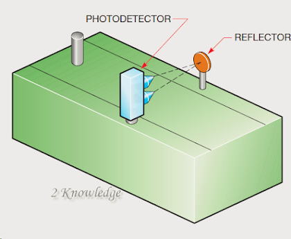
Photodetectors with both the transmitter and receiver parts housed in the same enclosure rely on a reflector to function. This sort of equipment is shown placed on a conveyor line in Figure 4-24. The reflector is the target of the transmitter. The light beam is returned to the receiver. The light reaching the receiver is obstructed when an item passes between the photodetector unit and the reflector. This sort of unit has the benefit of requiring only one piece of equipment to be electrically connected. This allows for simple attachment of the photodetector unit as well as mounting of the reflector in tough-to-reach locations where running control wiring would be problematic. Many of these devices have a 20-foot or greater range.
Figure 4-24 Shows When an item passes between
the photodetector and the reflector, it is detected.
An optical fiber cable is used in another sort of unit that works on the concept of reflected light. The cable’s fibers are split in half. The transmitter is attached to half of the fibers, while the receiver is connected to the other half (Figure 4–25). This item has the benefit of allowing the transmitter and receiver to be installed in a very tiny space.
Figure 4-255 Shows Light is sent and received through optical cable.
Figure 4-26 depicts a common use for this sort of device. The device is used to operate a label-cutting machine. Labels are produced on a big roll and must be cut for each shipment. The label roll has a narrow dark-colored strip on one side with glossy parts set at regular intervals.
Figure 4-26 Shows The optical wire detects a gleaming
region on one side of the label.
Above this small strip is the optical fiber wire. When the strip’s black surface passes beneath the optical wire, no reflected light returns to the receiver device. Light is reflected back to the receiver device as the shining part passes beneath the wire. The photodetector transmits a signal to the control circuit, instructing it to clip the label.
Photodetectors are extremely reliable and have a stellar maintenance and service track record. They can detect practically any thing without making direct touch with it, and they can do so millions of times without harm or wear. Figure 4-27 shows a photodetector.
Figure 4-27 Shows Photodetector equipment
that includes both a transmitter and a receiver.