Getting Started with Arduino to knows everything about Arduino.
Getting Started with Arduino environment has been designed to be simple to use for newcomers with no prior software or electronics skills. If you are new to Arduino, this post will get you started, but you will need to study the Arduino online help and a decent Arduino book (the author’s “Arduino Cookbook” is highly recommended as a reference).
Although Arduino is best known for its hardware, programming that hardware requires software as well. The hardware and software are both referred to as “Arduino.” You may use this combo to construct projects that perceive and control the physical world. The program is open source, free, and cross-platform. You may buy the boards cheaply or make your own (the hardware designs are also open source). Furthermore, there is an active and supportive Arduino community that is available globally via the Arduino forums and the wiki (known as the Arduino Playground). The forums and wiki give project development examples and problem solutions that can serve as inspiration and aid while you work on your own projects.
This post will get you started by showing you how to set up the development environment and build and execute an example sketch.
In the Arduino community, source code providing computer instructions for managing Arduino functionality is commonly referred to as a sketch.
Throughout this book, the term sketch will refer to Arduino program code.
Getting Started with Arduino
Programming Arduino
Hardware Required
• Computer with Arduino 1.0.1 or later installed
• Leonardo (or Uno) Arduino board
• Motor Shield
• USB cable
Arduino Software
Using the Arduino integrated development environment, computer users may construct software programs, or sketches (IDE). With the help of the IDE, you can create and change code and translate it into commands that the Arduino hardware can follow. Additionally, those instructions are uploaded to the Arduino board by the IDE.
Arduino Hardware
The Arduino board is where your written code is put to use. Specific parts are added to the board to let it to interface with the outside environment because it can only regulate and react to electricity. These parts can be actuators, which take energy from the board and transform it into something that alters the environment, or sensors, which turn a physical feature of the world into electrical so that the board can perceive it. Switches, accelerometers, and ultrasonic distance sensors are a few examples of sensors. Lighting and LEDs, speakers, motors, and screens are examples of actuators.
Both official boards and community-produced boards that are Arduino-compatible are available for you to use with your Arduino sketches.
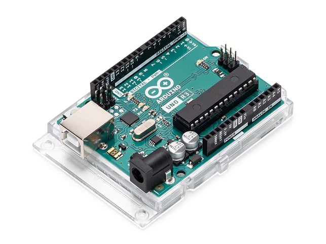
The majority of boards come with a USB port, which is used to power and connect the board while you upload your program. The Arduino Leonardo board, which is utilized for the robots in this book, is seen in Figure 5-1.

Figure 5-1 shows the Arduino Leonardo’s basic board.
Boards with more connections and smaller boards are both available. These robotics projects use the Leonardo since it is less expensive, but if you like, you may use other boards like the Uno.
It’s possible that you’ll need to use a little higher voltage (an extra battery) to power the robot if you wish to utilize an Uno board (or previous Arduino boards),
Shields are auxiliary boards that connect to Arduino and increase its hardware capabilities. Figure 5-2: The robots described in this book employ a shield to regulate the direction and speed of the motors.

Figure 5-2 shows the Arduino Leonardo with the Motor Shield attached.
Installing the Integrated Development Environment (IDE)
The ZIP file used for the Windows download. Any handy location, such as Program Files/Arduino, should be used to unzip the file to.
The folder Arduino-1.0.nn> (where nn is the version number of the Arduino release you downloaded) will be created when the file is unzipped. Along with a number of other files and directories, the directory also includes the executable file, which goes by the name Arduino.exe. The splash screen (see Figure 5-3) and main program window (see Figure 5-4) should both show when you double-click the Arduino.exe file. The program may take some time to load, so be patient.

Figure 5-3 shows the Arduino splash screen (Version 1.0 in Windows 7)
Arduino Installation on Mac OS X
The Arduino download for Mac is a disc image (.dmg); once downloaded, double-click the file. The picture will mount (it will show on the desktop as a memory stick). The Arduino application is contained within the disc image.
Copy this to a handy location—the Applications folder is a good choice. Once copied, double-click the application (running it from the disc image is not recommended). The splash screen will be displayed first, followed by the main application window (Figure 5-4).

Figure 5-4: The primary window of the IDE (Arduino 1.0 on a Mac)
Installation of Drivers
The operating system must utilise the necessary drivers for your board in order for the Arduino development environment to interface with it.
Connect your PC and the Arduino board with a USB cord in Windows and wait for the Found New Hardware Wizard to appear. Allow the wizard to try to discover and install drivers if you’re using a Leonardo or Uno board.
Troubleshooting the Found New Hardware Wizard
If the Found New Hardware Wizard does not show when you connect a Leonardo board for the first time, open Device Manager as stated below, and if you see Other device> Arduino Leonardo with an exclamation point, right click on the item and select Update Driver Software. Select Browse my computer for Driver Software and go to the Drivers folder within the Arduino folder you just unzipped. After selecting the drivers folder, Windows should begin the installation procedure. If the Windows can’t verify the publisher of the driver software prompt appears, click Install anyhow.
If the Wizard begins but fails to identify drivers (don’t worry, this is normal for an Uno board). To resolve the issue, navigate to Start>Control Panel>System and Security. Open Device Manager after clicking on System. Find the entry in COM and LPT called Arduino UNO in the presented listing (COM nn). nn is the number that Windows has allocated to the board’s port. Because the relevant drivers have not yet been allocated, you will see a warning emblem next to this. Select Update Driver Software from the context menu when you right-click on the item.
Select Browse my computer for Driver Software and go to the Drivers folder within the Arduino folder you just unzipped. After selecting the ArduinoUNO.inf file, Windows should begin the installation procedure. If Windows cannot verify the publisher of the driver software, choose Install this software anyhow.
If you are online and using an older board (any board that utilizes FTDI drivers) with Windows Vista or Windows 7, you may let the wizard search for drivers, which will install them automatically. You must provide the location of the drivers on Windows XP (or if you do not have internet access). Navigate to the FTDI USB Drivers directory, which is located in the location where you unzipped the Arduino files, using the file selector. After installing this driver, the Found New Hardware Wizard will display again, indicating that a new serial port has been discovered. Continue in the same manner as previously.
The newest Arduino boards may be utilized on the Mac without the need for extra drivers. When you initially connect the board, a message will appear stating that a new network port has been discovered; you can disregard this. If you’re using an older board (one that requires FTDI drivers), you’ll need to install driver software. Inside the Arduino installation disc image is a package called FTDIUSBSerialDriver, followed by a string of numbers. When you double-click it, the installer will walk you through the installation. To finish the procedure, you will need to know an administrator password.
Connecting the Arduino Board
Connect the board to a USB port on your computer and ensure that the board’s green LED power indicator glows. Figure 5-5 shows the placement of the LED.

Figure 5-5. shows The Leonardo
When you turn on the board, an orange LED (designated “Pin 13 LED” in Figure 5-5) should blink on and off (boards come from the factory preloaded with software to flash the LED as a basic check that the board is operating).
If the power LED does not light up when connected to your computer, the board is most likely not receiving power.
Using the IDE
Create, open, and change sketches that specify what the board will perform using the Arduino IDE. To conduct these activities, you may utilize the buttons along the top of the IDE (shown in Figure 5-6), or you can use the menus or keyboard shortcuts (some are shown in Figure 5-7).

Figure 5-6. shows Arduino IDE
The Sketch Editor section is where you may examine and change sketch code. It recognizes typical text editing shortcuts such as Ctrl-F (-F on a Mac) for find, Ctrl-Z (-Z on a Mac) for undo, Ctrl-C (-C on a Mac) for copying highlighted text, and Ctrl-V (-V on a Mac) for pasting highlighted text.
Figure 5-7 explains how to load the Blink program (which is preinstalled on a new Arduino board).
After starting the IDE, navigate to the FileExamples menu and choose 1.Basics Blink, as shown in Figure 5-7. In the Sketch Editor window, the code for flashing the built-in LED will be presented.

Figure 5-7 shows the IDE menu (selecting the Blink example sketch)
Before the code can be delivered to the board, it must be compiled into instructions that can be read and performed by the Arduino controller chip. To do so, choose SketchVerify/Compilation (Ctrl-R, -R on a Mac) or click the compile button (the top-left button with a tick within).
In the message box below the text editing window, you should see a message that says “Compiling sketch…” and a progress meter. After a few seconds, a notification stating “Done Compiling” will show. The following message will be shown in the dark console area:
Binary sketch size: 1026 bytes (of a 32256
byte maximum)
The precise message may vary based on your board and Arduino version; it will inform you the size of the sketch as well as the maximum size that your board can tolerate.
The last message informing you of the sketch’s size specifies how much program space is required on the board to store the controller instructions. If the compiled sketch’s size exceeds the available memory on the board, the following error message is displayed:
Sketch too big
Troubleshooting #size for tips on reducing it.
If this occurs, you must either reduce the size of your sketch to fit on the board or get a board with a larger capacity. This is not a problem with the Blink sample sketch.
If the code contains errors, the compiler will display one or more error messages in the console window. These alerts can aid in the identification of the mistake.
As you build and edit a drawing, try utilizing the FileSave As menu option with a different name or version number on a regular basis so that you may go back to an earlier version if necessary.
Blink Sketch Uploading and Running
Connect your Arduino board to your computer using the USB connection to transfer your compiled sketch to the Arduino board. Load the sketch into the IDE using the instructions in “Using the IDE.”
Next, pick ToolsBoard from the drop-down box and enter the name of the connected board.
Select ToolsSerial Port now. You will be presented with a drop-down list of serial ports on your computer. Depending on what other devices you have connected to your computer, each machine will have a unique assortment of serial ports.
They will appear as numbered COM items in Windows. If there is just one option, choose it. If there are numerous submissions, your board will most likely be the last.
Your board will be listed twice on the Mac (you may use either one):
/dev/tty.usbmodemXXXXXXX
/dev/cu.usbmodemXXXXXXX
If you have an older board, it will be listed like this:
/dev/tty.usbserial-XXXXXXX
/dev/cu.usbserial-XXXXXXX
Each board will have a unique value for XXXXXXXX. Choose any option.
Click the upload button (the second from the left in Figure 5-6), or choose FileUpload to I/O board (Ctrl-U, -U on a Mac).
As described in “Using the IDE,” the program will compile the code. The program is uploaded to the board after it has been compiled. When you look at your board, you will see that the LED has stopped flashing and that two lights (designated as Serial LEDs in Figure 5-5) directly below the previously flashing LED should flicker for a few seconds as the code downloads. As the code executes, the original light should begin to flash again.
If the upload fails, the IDE will display an error message. Problems are frequently caused by selecting the incorrect board or serial port, or by not plugging in the board. The status bar at the bottom of the Arduino window displays the presently chosen board and serial port.
If you’re having difficulties recognizing the proper port on Windows, try disconnecting the board and then choosing ToolsSerial Port to see which COM port is no longer shown. Another method is to choose the ports one by one until the lights on the board begin to flicker, indicating that the code is uploading.
Using Tabs
When your drawing grows in size, tabs provide a useful method to arrange code. It allows you to keep functionally similar code together and makes it easier to share this code across other sketches.
The arrow in Figure 5-8’s top right corner links to a button that opens a drop-down window with tab-related capabilities. This window displays the tab names and provides a list of commands:
• New Tab creates a new tab (you will be prompted to name the tab)
• Rename allows you to rename the presently selected tab.
• Delete removes the current tab (you are prompted if you are certain you want to do so).

Figure 5-8. shows IDE tabs
Each tab has its own file, and when you transfer these files to other sketches, the tab is added to that sketch.
Tabs are utilized frequently in this book since there are numerous functional modules that are common throughout most of the designs. Figure 5-8 depicts the myRobot design, which will be examined in the following chapter, and which employs tabs for infrared sensor code (irSensors) and program constants and definitions (robotDe fines.h).
Third-Party Library Installation
This book’s download code (see “How to Contact Us” (page xv)) includes three libraries that are necessary to execute all of the drawings detailed in the book. These libraries are located in the zip’s libraries subdirectory. You must copy these to a folder named libraries within your Arduino document folder. Open Preferences (ArduinoPreferences on Mac; FilePreferences on Windows) and note the sketchbook location. Navigate to that directory using a file system browser (for example, Windows Explorer or the OS X Finder) or the terminal. If no libraries folder exists, create one and place the unzipped folder within it.
Quit and restart the Arduino IDE if it is still running. Only when the IDE is opened does it check this folder for libraries. If you now go to the SketchImport Library menu, you should notice the library you added at the bottom, behind the grey line and the word Contributed.
Configuring the Library for Four Wheels
If your robot has four wheel drive, you must alter the RobotMotor library code to advise the compiler that the library should be produced for the 4WD chassis.
To change the RobotMotor.h file to utilize the 4WD chassis, first navigate to the Arduino preferences (FilePreferences on Windows or Linux, ArduinoPreferences on Mac). The name of the directory containing your sketches and libraries may be seen under Sketchbook Location. Next:
1. Launch the Finder (Mac) or Explorer and navigate to the sketchbook folder (Windows).
2. Navigate to the libraries directory and then to the RobotMotor directory.
3. Right-click the RobotMotor.h file and select Open with a Text Editor. You may use Notepad on Windows. TextEdit is available on the Mac. Use your preferred plain text editor on Linux.
4. Rename the file #define CHASSIS 2WD to #define CHASSIS 4WD and save it.
The libraries/RobotMotor/RobotMotor4wd subdirectory in the examples zip file contains a version of RobotMotor.h with the 4wd modification preset. When you copy this file to the RobotMotor folder, it will replace the 2wd version with the 4wd version.
If the libraries include example sketches, you may see them from the IDE menu; select FileExamples, and the library’s examples will be in a section between the general examples and the Arduino distributed libraries example listing, under the library’s name.
If the library examples do not display in the Examples menu or you receive an error message reading “Library not found” when you try to use the library, make sure the libraries folder is in the proper location and that the name is spelt correctly. A file named LibraryName> must exist in a library folder named LibraryName> (where LibraryName> is the name of the library). h, both in spelling and capitalization. Check that the folder contains any additional files required by the library.