Start with Sensors for Arduino & Raspberry Pi. Measure the World with Electronics, Arduino, and Raspberry PiTo create electronic projects that can sense the physical world, you’ll need to use circuits based on sensors, which are electronic components that send an electrical signal in response to physical events. You may make useful and educational sensor projects with only basic electrical components.
However, including Arduino or Raspberry Pi into your project allows you to create far more complex projects that can respond in unexpected ways and even connect to the Internet. This post begins by showing you how to read and react to a sensor using simple electrical circuits. It then goes on to explain how to create sensor systems with Arduino, before concluding with a tutorial on how to create sensor projects with the Linux-powered Raspberry Pi.
You’ll get hands-on experience with some of the most helpful and informative sensors for Arduino accessible in this Post. You’ll learn how to detect and respond to the following sensors and applications using the sensors and apps in this post:
- A potentiometer clicks and rotates.
- Proximity using infrared sensors
- Distance with ultrasound
- Photoresistor for light and dark
- Thermometer for temperature
- Capacitive relative humidity sensor for relative humidity
Start with Sensors for Arduino
1- Sensors for Arduino
Sensors are all around you in your daily life. Sensors are all around us, from passive infrared sensors in motion detectors to CO2 detectors in air conditioning systems and even small accelerometers, GPS modules, and cameras within your smartphone and tablet. The range of sensor applications is astounding.
It’s reasonable to assume that if an electrical item is labelled “smart,” it’s jam-packed with sensors (Figure 1). Indeed, the proliferation of smart gadgets, particularly smartphones, has driven down the cost of sensors. Adding sophisticated sensors for Arduino to your projects is not only cost-effective, but it also dramatically expands the types of projects you may create.
In this post, you’ll learn about sensors for Arduino by doing little projects and reflecting on your experiences. It’s more enjoyable to construct first and then talk, but both are vital. It’s wise to resist the urge to skip the conceptual parts in favor of merely building projects.
Getting started using sensors for Arduino is simple, and the only restriction is your imagination. Every day, electronics challenges some of the brightest minds, resulting in new discoveries and dissertations. On the other hand, with some guidance, even a youngster can get started.
If you don’t know much about sensors yet, try to recall how you feel right now. Many dark mysteries of sensors will probably appear common sense to you after you’ve faced some obstacles and constructed a handful of devices.

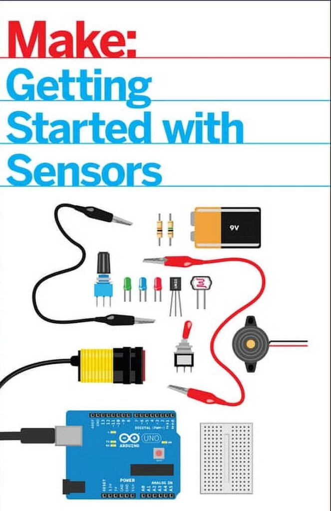
Figure 1-1. Various sensors: infrared proximity, rotation, brightness, button, temperature, and distance
This post is appropriate for anyone who is interested in sensors (see Figure 1–2).
What exactly are sensors? sensors for Arduino are electrical devices that serve as input devices. Although not all inputs are specifically sensors, practically all inputs make use of sensors! Consider a computer mouse or trackpad, a keyboard, or even a webcam; these are not sensors, yet they are designed with sensors in mind.
In a broader sense, sensors for Arduino may be thought of as a component that measures a stimulus that is external to the system in which they are installed (its environment). The measurement is used to generate the output data. When you type on a keyboard, for example, the letter that shows on your screen (the output) is determined by the measurement (which switch or key you pressed on the keyboard).
Another measurement (how long you hold the key pushed) determines how many letters display on the screen.

Figure 1-2: A four-year-old developed and designed this simple AND connection with buttons with the assistance of an adult.
The first project measures light with a photoresistor. There is no way for the circuit to know how bright the light is in the surroundings without the photoresistor (or equivalent sensor). Your circuit now knows something it didn’t know before you added the sensor.
All of the projects in this post assess a specific stimulus in the environment.
Without sensors for Arduino, none of this would be possible. Let’s get started so you can see the inputs and outputs that sensors bring to projects.
Project 1: Light Measurement Using a Photoresistor
Light in an environment is extremely informative: you can tell what time of day it is by the angle of the sun, you can drive a car more securely at night when its lights are on, and those who do not get enough light in their daily lives can get seasonal affective disorder. As a result, light impacts many elements of your life, and it’s also entertaining to measure it.
A photoresistor is the most basic sensor for sensing light. It’s pretty unusual to come across another term for the same sensor: light-dependent resistor (LDR). The component functions by adjusting its resistance in response to the quantity of light that strikes it.
Now that you’ve determined the sensor to utilize, the next item to consider is how to handle the sensor’s readings. If you’ve ever dealt with a light-emitting diode (LED), as illustrated in Figure 1–3, you may be aware that resistance is a significant electrical factor. For example, if you’ve ever used a higher-value resistor for an LED than the project allowed for, you’ll know that too much resistance might prevent an LED from glowing. This same fundamental insight applies to this endeavor.

Figures 1–3. LEDs
The circuit is built in such a way that the measurement of the photoresistor determines the behavior of an LED. If there is too much resistance, the LED will not turn on.
Enough with the philosophizing—time to go to work! Figure 1–4 depict the completed project.

Figure 1-4. The finished photoresistor project
Parts
This project requires the following components:
- Photoresistor.
- 5 mm red LED (various LEDs will behave differently with this circuit; you’ll learn a more advanced approach to fade LEDs later).
- 470Ω resistor (four-band resistor: yellow-violet-brown; five-band resistor: yellow-violet-black-black; the last band varies depending on resistor tolerance)
- Breadboard
- 9-volt battery clip
- 9-volt battery
Note…
Except for the 9 V battery and 470 resistor, all of these components are available in the Maker Shed Mintronics: Survival Pack, part number MSTIN2. You may use two 220 resistors in series or one 1 k resistor for the 470 resistor; both are available from electronics merchants such as RadioShack.
Build It
Here are the steps for building this project:
1. Position your breadboard so that it is wider than tall, as indicated in Figure 1–5.

Figure 1-5. Circuit diagram for the Photoresistor Project
2. Examine your LED and note which lead has a flat side above it on the colored plastic housing—this is the negative lead (the negative lead is also the shortest of the two), as illustrated in Figure 1–6. LEDs have a certain polarity, and plugging them in backwards may cause harm.

Figure 1-6. Negative leg of the LED
3. Place the photoresistor such that the LED’s negative lead and one of the photoresistor leads are in the same column. For the time being, the second (positive) LED led should be in its own column. Refer to Figure 1–5 for an example of how they should be placed.
Note…
Is the space in the center of the breadboard visible in Figure 1–7? There is no link across the gap that divides the two sets of columns. If you wish to join two leads in the same column, make sure they are on the same side of the gap.

Figure 1-7. Breadboard layout
4. Connect the 470Ω resistor to the column with the positive LED lead, making sure it’s not the same column with the photoresistor and LED’s negative lead already connected. Check that the resistor’s other lead is in a different column.
5. Connect the battery clip’s black wire to the column that only has a photoresistor lead.
6. Connect the red wire from the battery clip to the column using just a resistor lead.
7. Double-check the instructions, then connect the 9-volt battery if everything appears as shown in Figure 1–5.
That’s all. You have completed your first sensor circuit. Congratulations!
Photoresistors are being discussed.
The circuit may not appear to be accomplishing anything. This is because the light levels in your room have most likely not altered significantly. Place your finger over the photoresistor and keep an eye on the LED. Did the LED appear to have changed in any way? The brightness of the LEDs should have changed. Increase the amount of light passing through the photoresistor. Didn’t the opposite happen? Now that you’ve seen the photoresistor in action, how would you characterize what happens in terms of resistance when you expose the photoresistor to more light? When the sensor is exposed to additional light, does the resistance increase or decrease?
Here’s a look at what’s going on on the circuit. The photoresistor’s resistance decreases as more light strikes it. If the environment is really bright, the LED will be quite bright as well. When the light in the room is low, the sensor inhibits current flow, causing the LED to fade.
The amount of current flowing through the sensor determines how bright the LED will be.
This is due to the fact that the circuit is built in such a way that all current to the LED must first travel via the photoresistor.
Electro-mechanical sensors are another sort of sensor. Changes in physical qualities, rather than changes in voltage or current, are manifested by these sensors.
The thermostat in your house or apartment is a good illustration (unless it’s a digital thermostat).
When the temperature in a room changes, the bimetallic coil in a thermostat will expand or contract depending on whether the temperature rises or falls. The sensor is really expressing itself physically by altering form! However, even these senses can cause an electronic sensor to be triggered (for example, a thermostat’s bimetallic coil is commonly coupled to a tilt switch that controls whether the heat is on or off).
Note…
As you may have guessed, a photoresistor is a resistive sensor. There are many different varieties of resistive sensors; this sort of sensor is used to measure much more than brightness. As you continue reading and come across different sensors, consider how the stimuli are measured and, more importantly, how the output is arranged. None of the sensors will produce data in a format that is suitable for end-user use. Instead, you must select how to describe or arrange the raw sensor data generated in a way that is understandable to consumers.
Interactive Sensors for Arduino Control
“Project 1: Photoresistor to Measure Light” employed a sensor in a manner that did not directly entail interaction with a human. Sure, you adjusted the illumination in the room to compel the photoresistor to change its resistance, but it could just as well have been the sun setting or rising.
Going Forward
You’ll be developing little systems that collect input data by collecting measurements using a sensor in all of the projects in this post. The systems will do something to process the input data and then act on it (the output of the system). At first, you’ll merely utilize electronic components to make things, but later in this post, you’ll use Arduino and Raspberry Pi to handle the processing.
You’ll develop code that handles a lot of the work for you when you utilize Arduino and Raspberry Pi. The advantage will become evident when you discover that you can modify the way you respond to an input without having to redesign your circuit.
Assume you wish to compete with a friend to determine who can press a force-sensing resistor down the hardest. All you’d have to do is add a few lines of code to the Arduino sketch and submit the updated code. How would you pull off the same ruse if you didn’t have the flexibility to change the code? It would certainly be more difficult, and you would have to rearrange a few things on the breadboard at the very least. And how would you present the contest outcomes’ score? It turns out that an Arduino can do a lot of things for you! However, this is not the entire tale of sensors.
We don’t want you to believe that as sensor systems’ physical complexity increases, so will their programming. Rather, we want you to consider this as a matter of applicability: what is the optimal design to achieve your goal?
Next post about Basic Sensors, Project 2: A Simple Switch, & Project 3: Buzzer Volume Control
To be continued…