Contactors and Relays
Relays
Relays are electromechanical switches with additional connections.
Auxiliary connections are tiny and designed for control purposes. They are not designed to regulate high quantities of current in general. Most relay current ratings range from 1 to 10 amps, depending on the brand and kind of relay. Figure 1-1 depicts a relay with a clapper. When the coil is turned on, the armature is drawn to the iron core within the coil.
Figure 1–1 Shows A magnetic relay is basically a solenoid with movable contacts attached.
As a result, the moveable contact separates from one fixed contact and connects to another. The common terminal is linked to the armature, which is the relay’s moveable component. The armature is connected to the moveable contact. The typically closed and normally open contacts are formed by the two stationary contacts.
When electricity is withdrawn from the coil, a spring restores the armature to its typically closed position. The shade coil is required to keep the contacts from chattering. A shade coil is required for all alternating current solenoids. They are not required for direct current relays. Figure 1-2 depicts a clapper style relay.
Figure 1-2 A clapper relay with one moveable contact and two stationary contacts.
This is a single-pole, double-throw relay.
Bridge Type of Relays
A bridge type relay works by dragging a metal piece or plunger within a coil (Figure 1–3). The plunger is linked to a bar with moveable contacts. The moveable contacts are spring-mounted and insulated from the bar. The plunger and bar assembly are referred to as the armature since they are the relay’s moving parts. Bridge contacts get their name from the fact that when the solenoid coil is activated and the plunger is dragged within the coil, the moving contacts bridge over the two fixed contacts. Bridge contacts may manage greater voltage than clapper contacts because they break the connection at two points rather than one.
Figure 1-3 One moving and two fixed contacts are used in bridge contacts.
They can manage greater voltages since the connection is broken at two points rather than one.
When the electricity is disconnected from the coil, gravity or a spring restores the moveable contacts to their original position. Figure 1-4 depicts a relay with bridge type connections.
Figure 1–4 Shows A relay with bridge type contacts.
Electromagnet Construction of Relays
The electromagnetic portion of a relay or contactor is built differently depending on whether it will be operated by direct or alternating current. Direct current relays and contactors typically have solid core materials, whereas alternating current relays and contactors have laminated cores.
The fundamental reason for the laminated core is the alternating current core losses induced by the constantly changing electromagnetic field.
Core Losses
Currents are induced into the metal core material as the magnetic field’s amplitude and polarity fluctuate continuously. These currents are referred to as eddy currents because they resemble eddies (swirling currents) seen in rivers. Heat is produced as eddy currents whirl about inside the core material (Figure 1–5). Laminated cores are made by stacking thin metal sheets together. Between the laminations, a thin layer of oxide develops. This oxide is an insulator that aids in the reduction of eddy current generation.
Figures 1–5 Shows Eddy currents are induced in the metal core,
resulting in heat loss and power loss.
Hysteresis loss is another form of core loss linked with alternating current devices. The molecules inside magnetic materials change direction, causing hysteresis loss. Magnetic domains or magnetic molecules exist in magnetic materials such as iron or mild steel. These are found in an unmagnetized chunk of material.
Magnetic domains are not arranged in any certain sequence (Figure 1–6). When the metal is magnetized, the magnetic molecules or domains align in an ordered pattern (Figure 1–7).
Figures 1–6 Shows A chunk of unmagnetized metal has its molecules in disorder.
Figures 1–7 Shows The molecules are arranged in a magnetic metal piece.
If the magnetic field’s polarity is reversed, the molecules will realign to the new polarity (Figure 1–8).
Although the domains will realign to conform to a polarity shift, they will fight the realignment. Power loss in the form of heat is necessary to cause them to shift polarity. Because the molecules in an alternating current field are constantly changing direction, hysteresis loss is also known as molecular friction.
The loss of hysteresis is proportional to the frequency. It is typically so little at low frequencies, such as 60 hertz, that it is unimportant.
Figures 1–8 Shows When the magnetic
polarity changes, all of the molecules move.
Coil Shading
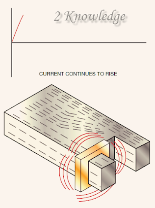
As previously stated, all solenoid-type devices that work on alternating current include shade coils to reduce chatter. In an alternating current circuit, the current continuously increases from zero to a maximum value in one direction, returns to zero, and then increases to a maximum value in the other direction (Figure 1-9). Because the current is constantly dropping to zero, when the magnetic field collapses, the solenoid spring or gravity will try to drop the armature out.
Figures 1–9 Shows The amplitude and direction of current in
an alternating current circuit are constantly changing.
To avoid this, shading coils create a temporal delay for the magnetic field. Magnetic lines of flux concentrate in the metal pole piece when current increases from zero (Figure 1–10). This growing magnetic field cuts the shade coil and causes a voltage to be induced in it. The shade coil or loop has a very low resistance since it is made of strong copper. A little induced voltage can cause a significant quantity of current to flow through the loop. A magnetic field is formed around the shading coil as a result of the current flow in the shading coil.
Fig. 1-10 A magnetic field is focused in the pole
piece when current begins to increase.
This magnetic field operates in opposition to the pole piece’s magnetic field, causing it to bend away from the shading coil (Figure 1-11). A voltage will be induced in the shading loop as long as the amplitude of the AC current changes.
Fig. 1-11 The magnetic field of the shading coil bends away from
the pole piece and concentrates on the unshaded portion of the pole piece.
When the current reaches its highest or peak value, the magnetic field ceases to change and no voltage is produced in the shade coil. Because there is no current flow in the shade coil, there is no magnetic field to counteract the magnetic field of the pole piece (Figure 1–12).
Fig. 1-12When the current reaches its maximum amount, the magnetic field ceases to change,
and the shade coil provides no resistance to the pole piece’s magnetic field.
The magnetic field of the pole piece begins to collapse as the current decreases. The falling magnetic field produces a voltage into the shading coil once more. Because the collapsing magnetic field is travelling in the other direction, the voltage generated into the shade coil forces current to flow in the opposite direction, generating an opposite polarity magnetic field surrounding the shading coil.
The shade coil’s magnetic field is now attempting to maintain the collapsing magnetic field of the pole piece (Figure 1-13). The magnetic flux lines of the pole piece concentrate in the darkened area of the pole piece as a result.
Fig. 1-13The shrinking magnetic field produces a voltage into the shading
coil as the current diminishes. The magnetic field of the pole piece is now aided
by the shading coil, and flux lines are focused in the shaded area of the pole piece.
The shade coil maintains a constant magnetic field around the pole piece, preventing the armature from falling out. Figure 1-14 depicts a laminated pole piece with shading coils.
Fig. 1-14 Shade coils on a laminated pole piece.
Control Relay Types
Control relays are available in a number of forms and kinds (Figure 1–15). Most feature various sets of contacts, and some are designed such that their contacts may be configured to be generally open or normally closed. In many cases, this flexibility may be really beneficial. When building a control circuit, one relay may require three ordinarily open and one normally closed contacts, but another may require two normally open and two normally closed contacts.
Fig. 1-15 Control relays are available in a range of case types.
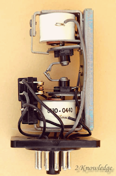
Many applications require relays that can be plugged into eight- or eleven-pin tube sockets (Figure 1–16). These relays are reasonably priced, and replacement is quick and straightforward in the case of a failure. Because the relays plug into a socket, the wire connects to the socket rather than the relay.
Fig. 1-16Relays that fit into eight- and eleven-pin tube sockets.
It is just a question of removing the faulty relay and replacing it with a new one. Figure 1-17 depicts an eleven-pin tube socket. Different coil voltages are available for eight- and eleven-pin relays. Common coil voltages include 12 volts DC, 24 volts DC, 24 volts AC, and 120 volts AC. Depending on the relay type and manufacturer, their contact ratings typically range from 5 to 10 amps.
Fig. 1-17 Shows 11-pin tube socket.
Figure 1-18 depicts the wiring diagram for eight- and eleven-pin relays. Holding the relay with the bottom facing you will reveal the pin numbers for eight- and eleven-pin relays. Turn the relay so that the key faces down. Figure 5-18 shows how the pins are numbered. The relay’s eleven pins house three distinct single-pole double-throw contacts. Pins 1–4, 6–5, and 11–8 are typically closed contacts. Contacts 1 and 3, 6 and 7, and 11 and 9 are generally open. Pins 2 and 10 are linked to the coil.
Fig. 1-18 Shows Eight- and eleven-pin relay connection diagrams.
The eight-pin relay has two individual single pole double-throw connections. Pins 1 and 4, as well as pins 8 and 5, are generally closed. Pins 1 and 3, as well as pins 8 and 6, are generally open. Pins 2 and 7 are linked to the coil.
Solid State Relay
The solid-state relay is another form of relay that is used in various applications. To connect the load to the line, solid-state relays use solid-state devices rather than mechanical contacts. A triac is a device used in solid-state relays that link alternating current loads to the line. The triac is a bidirectional device, which implies that current can flow in either direction via it. There are several techniques for controlling when the triac goes on or off. One way makes use of a tiny relay device to regulate the triac’s gate (Figure 1–19). A low voltage source can be used to control the relay.
Fig. 1-19 A solid-state relay that controls the activity of a triac via a reed relay.
When the relay contact is activated, it closes, sending power to the gate of the triac that links the load to the line. Optoisolation, or optical isolation, is another frequent approach for regulating the operation of a solid state relay. Many PLCs utilize this way to interact with the output device. Optoisolation is accomplished by energizing a photo triac with light from a light-emitting diode (LED) (Figure 5–20).
When a diode is activated, the arrows pointing away from it indicate that it emits light. The arrows pointing toward the triac symbol indicate that it must be illuminated in order to turn on.
Because there are no moving contacts to wear and the load side of the relay is electrically separated from the control side, optical isolation is particularly popular with electronic equipment such as computers and PLCs. This isolation keeps any electrical noise created on the load side from reaching the control side.
Fig. 1-20 A solid-state relay controls the operation of a triac via optical isolation.
To regulate loads linked to direct current circuits, solid-state relays are also available (Figure 1–21).
To link the load to the line, these relays employ a transistor rather than a triac.
Fig. 1-21 A solid-state relay that regulates a direct current load connects
the load to the line through a transistor rather than a triac.
Solid-state relays are available in a wide range of case types and ratings. Some have a voltage rating of 3 to 30 volts and can only regulate a tiny amount of current, but others can manage hundreds of volts and many amperes. Figure 1-22 depicts an eight-pin IC (Integrated Circuit) with two solid-state relays suitable for low-power applications.
Fig. 1-22 Two low-power solid-state relays are housed in an eight-pin integrated circuit.
Figure 1-23 shows a solid-state relay rated to regulate an 8-ampere load connected to a 240-volt AC circuit. To regulate that level of power, this solid-state relay must be installed atop a heat sink to boost its capacity to disperse heat. Although rated at 240 volts, this relay may also control devices at lower voltages.
Fig. 1-23 Solid-state relay capable of controlling 8 amps at 240 volts.
Contactors
Contactors are electromechanical devices that are comparable to relays. Contactors with coils intended for usage at higher voltages are available.
The majority of relays. The majority of relay coils are designed to function on voltages ranging from 5 to 120 volts AC or DC.
Contactors are available with coil voltage ranges ranging from 24 to 600 volts. Although higher voltage coils are available, for safety concerns, most contactors work on voltages that do not exceed 120 volts. By adjusting the coil, contactors may be modified to work on different control circuit voltages. Manufacturers design coils to work with various types of contactors.
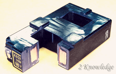
Most have several twists of wire and are housed in a plastic casing that may be changed by dismantling the contactor (Figure 1–24).
Fig. 1-24 The magnetic coil has been removed to reveal insulated copper
wire coiled on a spool and covered by a molding.
NEMA regulations require the magnetic switch device to function reliably at voltages ranging from 85% to 110% of the specified coil voltage. Voltages can vary from one region of the nation to another, and voltage fluctuation is common inside a facility as well. Excessive coil voltage draws too much current, causing the insulation to overheat and finally burn out.
Excessive voltage also causes the armature to smash against the stationary pole pieces, causing fast wear of the pole pieces and shortening the life of the contactor.
Another impact of high voltage is wear produced by moving contacts crashing into stationary contacts, resulting in excessive contact bounce. Contact bounce can result in arcing, which generates extra heat and wear on the contacts.
Inadequate coil voltage can cause just as much, if not more, harm as high voltage. If the coil voltage is too low, the coil will have less current flow, resulting in a weaker magnetic circuit than usual. The armature will pick up but will not entirely seal against the stationary pole components. This might result in an air gap between the pole parts, which prevents the coil current from decreasing to its sealed value. Excessive coil current, overheating, and coil burnout result from this.
A weak magnetic circuit can cause the moveable contacts to meet the stationary contacts and connect, but not have enough force to allow the contact springs to produce sufficient contact pressure. This can result in arcing and potential contact welding.
High currents cause excessive heat and significantly reduce the life of the contacts if sufficient contact pressure is not used.
Load Contacts
The primary distinction between relays and contactors is that contactors have big contacts designed to connect high current loads to the power line (Figure 1–25). These huge connections are referred to as load contacts. Load contacts can be rated to regulate several hundred amps depending on their size.
Most will include some kind of arcing chamber to assist extinguish the arc created when large current loads are unplugged from the power line. Figure 1-25 depicts arcing chambers.
Fig. 1-25 Contactors have load connections
that link high current loads to the power line.
Other connections may have arc chutes that assist extinguish the arc by extending its route. When the contacts open, the heat created by the arc causes the existing arc to increase (Figure 1–26). The arc chute’s horns drag the arc farther and farther apart until it can no longer support itself. The blowout coil is another gadget that works on a similar basis.
Fig. 1-26 Heat causes the arc to climb between the arc chutes.
Blowout coils are often utilized on direct current contactors and are coupled in series with the load (Figure 1–27). When the contact opens, the arc is drawn to the magnetic field and rapidly rises. This is the same basic movement that causes a direct current motor’s armature to revolve.
Fig. 1-27 To create a magnetic field, magnetic blowout
coils are connected in series with the load.
Because the arc is a flow or current, a magnetic field occurs around it. The magnetic field of the arc is attracted to the magnetic field created by the blowout coil, forcing the arc to rise.
The arc is extinguished at a faster pace than an arc chute, which relies on heat to propel the arc higher. Blowout coils are occasionally used on contactors that regulate huge quantities of alternating current, although they are more commonly utilized with direct current contactors. When the waveform goes through zero, alternating current cuts off every half cycle.
This aids in the extinguishment of arcs in alternating current circuits. Direct current, on the other hand, does not switch off at regular intervals. It is significantly more difficult to extinguish a DC arc after it has been developed.
Blowout coils are an efficient way to extinguish these arcs. Figure 1-28 depicts a contactor with a blown coil.
Fig. 1-28Contactor of the clapper type with a blown coil.
Most contactors include both auxiliary and load connections. If necessary, the auxiliary connections can be employed in the control circuit.
A three-pole contactor is used in Figure 1-29 to connect a bank of three-phase heaters to the power line. A typically open auxiliary contact controls an amber pilot light that indicates the heaters are turned on, while a normally closed contact controls a red pilot light that shows the heaters are turned off.
Fig. 1-29 The load and auxiliary contacts are both present in the contactor.
The activity of the HR contactor coil is controlled by a thermostat.
The typically closed HR auxiliary contact powers the red pilot light when it is de-energized. When the thermostat contact is closed, coil HR is activated and all HR contacts shift positions.
Close the three load connectors to connect the heaters to the line. When the typically closed HR auxiliary contact opens, the red pilot light is turned off, and when the normally open HR auxiliary contact closes, the amber pilot light is turned on. Figure 1-30 depicts a size 1 contactor with auxiliary contacts.
Figure 1-30 A contactor of size 1 with supplementary contacts.
Vacuum Contactors
Vacuum contactors have their load contacts enclosed in a vacuum chamber. A metal bellows linked to the moveable contact allows it to move without causing the seal to break (Figure 1–31). When contacts are sealed inside a vacuum chamber, they may switch greater voltages within a relatively narrow area between the contacts without causing an arc. Figure 1-31 shows connections rated at 7.2 kilovolts and 400 amps.
Fig. 1-31 Inside a vacuum chamber, vacuum contacts are sealed.
When the voltage between fixed and mobile contacts is high enough to ionize the air molecules, an electric arc is formed. Because there must be adequate space between the contacts to disrupt the arc path, medium voltage contactors are often huge.
To quench or prevent an arc, certain medium voltage contactors employ arc suppressors, arc shields, and oil immersion. Vacuum contactors work on the premise that if no air surrounds the contact, there is no ionization route for the formation of an arc. Vacuum contactors are often smaller in size than other medium voltage contactor kinds. Figure 1-32 depicts a three-phase vacuum contactor rated at 7.2 kilovolts and 400 amps.
Fig. 1-32 Vacuum contactor with three phases and
a rating of 7.2 kV and 400 amps.
Figure 1-33 depicts a three-phase vacuum contactor rated at 12 kilovolts and 400 amps.
Fig. 1-33 Three-phase vacuum contactor with a rating of 12 kV and 400 amps.
Mechanically Held Contactors and Relays
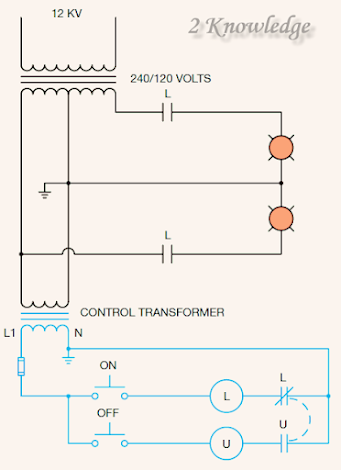
Latching contactors and relays are terms used to describe mechanically held contactors and relays. They are powered by two electromagnets. One coil is known as the latch coil, and the other as the unlatch coil (Figure 1–34). After power is disconnected from the latch coil, the contacts shift position and mechanically remain in place. The unlatch coil must be activated to restore the connections to their usual de-energized condition.
Fig 1–34 Shows Latching relay.
Figure 1-35 depicts a circuit with a latching relay. Power is supplied to both coils through momentary contact push buttons. Most mechanically held contactors and relays are designed for intermittent usage, and continuous power will frequently cause burnout.
When power is stopped, the contacts of latching relays and contacts do not return to their regular state, unlike ordinary magnetic contactors or relays. They should only be used where there is no threat of harming people or equipment if electricity is unexpectedly restored after a power outage.
Fig 1-35 A latch and unlatch coil is used
in latching type relays and contactors.
Sequence of Operation
Many latching relays and contactors have contacts that prohibit continuous power from being provided to the coil once it has been activated. These connections are sometimes referred to as coil cleaning contacts. L coil is the latching coil in Figure 1-35, and U coil is the unlatch coil. When the ON push button is pressed, electricity can travel to the L coil and then to neutral via the normally closed L contact. When the relay switches to the latch position, the usually closed L contact, which is linked in series with the L coil, opens and cuts power to the L coil. This prohibits any more power from being delivered to the L coil.
When the OFF push button is pressed, the open U contact linked in series with the U coil closes to allow U coil activity. When the L coil is turned on, it closes the L load contacts, so turning on a bank of lights. By pushing the OFF push button and activating the U coil, the lighting may be turned off. As a result, the relay returns to its original place. The coil clearing connections prohibit electricity from being provided continually to the mechanically held relay’s coils.
Mercury Relays
Mercury relays use mercury-wetted contacts rather than mechanical contacts. The electrode is the only stationary contact in a mercury relay.
Inside the electrode chamber is the electrode. When the coil is activated, a magnetic sleeve is drawn down within a pool of liquid mercury, forcing the mercury to rise in the chamber and contact with the fixed electrode (Figure 1–36). The advantage of mercury relays is that the contact is regenerated each time the relay is used, preventing burning and pitting produced by an arc when a connection is created or severed. Mercury relays have the drawback of containing mercury. Mercury is a hazardous chemical that has been linked to neurological and renal harm. Some European governments have outlawed the use of mercury.
Figure 1–36 Shows Diagram of a mercury relay.
Mercury relays must be installed vertically rather than horizontally. They come in single-pole, double-pole, and three-pole versions. Figure 1-37 depicts a singlepole mercury relay.
When the voltage is doubled, the size of the load connections is decreased since the current is halved for the same power rating.
Motor #1 must be started before motors #2 or #3 in the circuit seen in Figure 5-44. This is done by connecting usually open contacts to starting coils M2 and M3. The coil of a control relay is connected in parallel with motor starter coil M1 in the circuit seen in Figure 1-44A.
As a result, control relay CR will work in tandem with motor starting coil M1. Until motor #1 is going, the two usually open CR contacts prohibit motors #2 and #3 from starting. It is expected that two auxiliary connections have been added to motor starter M1 in the circuit depicted in Figure 1-44.
The two new auxiliary connections can be used to replace the two typically open CR contacts, removing the requirement for control relay CR. Figure 1-45 depicts a motor starter with additional auxiliary connectors.









হাই, আমি আপনার মূল্য জানতে চেয়েছিলাম.
Thank you.
Hi, I wanted to know the price.
It’s free courses.
You have no idea how much I want this