Uses of Float Switches or Sensors. When a pump motor must be started and stopped in response to variations in the water (or other liquid) level in a tank or sump, a float switch is employed. Float switches are intended to manage AC and DC pump motor magnetic starters as well as light motor loads automatically.
Types of Float Switches or Sensors
The upward or downward movement of a float in a water tank controls the operation of a float switch. The float movement opens or closes electrical connections using a rod-operated (Figure 3-1) or chain-and-counterweight (Figure 3-2) system.
The float switch contacts can be typically open or normally closed, and they cannot be submerged.
Depending on the contact design, float switches can be linked to a pump motor for tank or sump pumping activities or tank filling.
Figure 3–1 Shows Rod-operated float switch.
Figure 3-2 Shows A chain-operated float switch with normally
closed (NC) and ordinarily open (NO) wire symbols.
Floating Mercury Bulb Switch
The mercury bulb float switch is another form of float switch that has grown in popularity. This sort of float switch does not require a float rod or chain to function. A mercury bulb switch is represented by a rubber bulb attached to a conductor. Inside the bulb is a series of mercury contacts. When the liquid level falls below the bulb’s location, it is hanging vertically (Figure 3–3A). When the liquid level reaches the position of the bulb, it becomes horizontal (Figure 3–3B). This position shift modifies the condition of the contacts in the mercury switch.
Figure 3–3 Shows The mercury bulb type float switch
Because the mercury bulb float switch does not have a differential setting like the rod or chain type, it is essential to employ multiple mercury bulb float switches to regulate a pump motor. The liquid differential level is measured by dangling mercury bulb switches at various heights in the tank. Figure 3-4 shows how four mercury bulb type switches are used to power two pump motors and produce a high liquid level alert.
Figure 3-4 Shows The length of the conductor determines the float level.
Figure 3-5 depicts the control circuit. The float switch FS1 detects the lowest liquid level in the tank and turns off both pump motors. When the liquid level reaches that height, the float switch FS2 activates the first pump. If pump #1 is unable to manage the tank level, float switch FS3 will activate pump motor #2 if the liquid level rises to that level. The float switch FS4 activates a warning light and buzzer when the tank is close to overflow. The buzzer can be turned off by pressing the reset button, however the warning light will stay on until the water level falls below the level of float switch FS4.
Figure 3-5 Shows Two-pump control with warning of a high liquid level.
The Bubblers System
The bubbler system is another common way for sensing liquid level. This technique does not rely on float switches. Pressure switches detect the liquid level (Figure 3–6). One significant advantage of this system is that the pressure switches are positioned outside the tank, eliminating the need to open the tank to service the system.
Figure 3-6 Shows A bubbler system is used to detect the amount of liquid.
The bubbler system is linked to an air line that connects to a manifold and another line that runs down into the tank. The maximum air flow is adjusted using a manual valve. The bubbler system works on the idea that as the liquid level in the tank rises, more air pressure is required to push air down the tank’s line. A 1-square-inch column of water 26.7 inches tall, for example, weighs 1 pound. Assume a 10-foot-long pipe with an interior area of 1 square inch. To blast air through the pipe, 4.494 psi would be required.
120 in / 26.7 psi = 4.494 lbs.
A pressure of just 3.146 psi would be required if the water level was 7 feet high.
The pressure switches offer an exact estimate of the liquid level since the pressure required to bubble air through the pipe is directly proportional to the height of the liquid. By replacing the float switches in Figure 3-5 with pressure switches, the pressure switches depicted in Figure 3-6 might be utilized to regulate the two pump circuits previously explained.
Figure 3–7 Shows Operation of the microwave gauge.
The Microwave Level Gauge
The microwave level gauge works by sending a high frequency signal into a tank at around 24 gigahertz and then detecting the frequency difference between the return signal and the product (Figure 3-7). No mechanical device touches or is put into the product, which is a significant benefit of the microwave level gauge. The gauge is appropriate for determining the concentration of turbulent, aerated, solids-laden, viscous, corrosive fluids.
Figure 3–8 Shows Cut-away view of a microwave level gauge.
It’s also great with pastes and slurries. Figure 3-8 is a cutaway view of a microwave level gauge.
Figure 3–9 Shows Microwave level gauge with meter.
Flow Switch and Sensor
Flow Switches
Flow switches detect the passage of air or liquid through a duct or pipe. Because the sensor mechanism resembles a sail, air flow switches are sometimes known as sail switches (Figure 3–10). A snap-action micro switch is used to build the air flow switch. The tiny switch is linked to a metal arm. A thin metal or plastic piece is attached to the metal arm. The thin piece of metal or plastic has a big surface area and provides air resistance. When a substantial volume of air flows across the sail, enough force is generated to drive the metal arm to work the switch’s contacts.
Figure 3–10 Shows Air flow switch.
Air flow switches are frequently used in air conditioning and refrigeration circuits to provide a positive signal that the evaporator or condenser fan is functioning prior to allowing the compressor to start. Figure 3-11 depicts a circuit of this type. When the thermostat contact is closed, control relay CR is activated and all CR connections are closed. This activates the condenser fan motor relay (CFM) as well as the evaporator fan motor relay (EFM). Because of the two typically open air flow switches, the compressor relay (Comp.) cannot start. When both the condenser and evaporator fans turn on, air movement causes both air flow switches to close, completing the circuit to the compressor relay.
Fig. 3-11 Shows Before the compressor can start,
In this circuit, a usually closed overload contact is shown solely in series with the compressor contactor. A dashed line has also been drawn around the condenser fan motor and overload sign, as well as the evaporator fan motor and overload symbol. This means that the overload for these motors is on the motor itself and not in the control circuit.
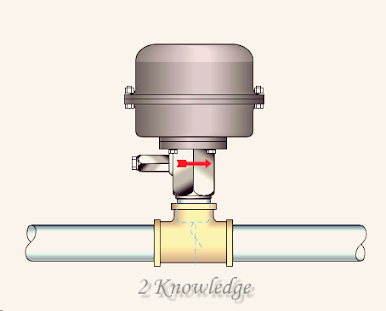
Liquid flow switches have a paddle that plugs into the pipe (Figure 3–12).
Figure 3–12 Shows Liquid flow switch.
Figure 3-13 shows how to install a flow switch by inserting a tee into the line. When liquid flows through the line, it exerts force on the paddle, causing the contacts to shift position.
Figure 3–13 Shows Flow switch installed in a tee.
Regardless of the flow switch type, they all have a single-pole double-throw micro switch (Figure 3–14). Flowswitches regulate low-current loads such as contactor or relay coils or pilot lights.
Figure 3-14: Shows Single-pole double-throw micro switch connections.
Figure 3-15 depicts a circuit that uses both the ordinarily open and usually closed contacts of a flow switch. The circuit is intended to control an air compressor’s functioning. The compressor is controlled by a pressure switch. A usually open push button is employed as a reset button in this circuit. Before electricity can be delivered to the remainder of the control circuit, the control relay must be activated.
Figure 3–15 Shows A red warning light indicates there is no oil flow.
Power is given to the lubrication oil pump relay when the pressure switch contact closes. Before the compressor can start, the flow switch monitors the flow of lubricating oil. It should be noted that a red caution light signals when there is no oil flow. To connect the flow switch in this circuit, connect power from the control relay contact to the flow switch’s common terminal so that power may be given to both the usually open and normally closed contacts (Figure 3–16). The typically open part of the switch is connected to the compressor contactor’s coil, while the ordinarily closed section is connected to the red pilot light.
Figure 3–16 Shows Connecting the flow switch.
The NEMA symbol is the same whether a flow switch is designed to detect the passage of air or liquid. Figure 10-8 depicts standard NEMA symbols for flow switches.
Figure 3–17 Shows NEMA standard flow switch symbols.
Flow Sensors
Movement switches are used to monitor the flow of liquid or air via a pipe or duct. Flow switches, on the other hand, are incapable of detecting the quantity of liquid or air flow.
A transducer is required to detect the amount of liquid or air flow. A transducer is a device that transfers one type of energy into a different type of energy. The kinetic energy of a flowing liquid or gas is turned into electrical energy in the case of a flow sensor. Many flow sensors are designed to output currents ranging from 4 to 20 milliamperes.
This current can be sent into a programmed controller or a meter intended to monitor the flow rate of the liquid or gas being metered (Figure 3–18).
Figure 3-18 Shows Several flow sensors are presented with
a meter to detect the flow rate of liquid.
Liquid Flow Sensors
There are various ways for measuring the flow rate of a liquid in a pipe. A turbine-type sensor is used in one way (Figure 3–19).
The turbine sensor is made up of a turbine blade that must be put into the liquid-filled pipe.
The turning of the turbine blade is caused by the flowing liquid.
The rotational speed of the blade is related to the quantity of flow in the pipe. The electrical output of the sensor is dictated by the speed of the turbine blade.
The turbine type sensor has one drawback in that the turbine blade provides some resistance to the flow of the liquid.
Figure 3–19 Shows Turbine type flow sensor
Electromagnetic Flow Sensors
The electromagnetic flow sensor is another form of flow sensor. These sensors work on the basis of Faraday’s Law for conductors travelling through a magnetic field. According to this rule, when a conductor passes through a magnetic field, a voltage is induced in the conductor. The quantity of induced voltage is related to the magnetic field intensity and the speed of the moving conductor. The flowing liquid is the conductor in the case of the electromagnetic flow sensor. Liquids should have a minimum conductivity of roughly 20 microhms per centimeter as a general rule.
Figure 3–20A Shows Operating principle
of an electromagnetic flow sensor.
Small electrodes installed within the sensor’s pipe monitor flow rate. The electrodes monitor the amount of voltage caused in the liquid as it travels through the sensor’s magnetic field (Figure 3-20A). Because the magnetic field intensity is known, the induced voltage will be proportional to the flow rate of the liquid. Figure 3-20B depicts a cut-away view of an electromagnetic flow sensor with a ceramic liner.
Figure 2-20B is a sectional view of an electromagnetic
flow sensor with a ceramic liner.
Orifice Plate Flow Sensors
Aperture plate flow sensors work by putting a plate with a known orifice into the flow stream (Figure 3–21). The plate is held in place by two unique flanges (Figure 3–22).
Figure 3–21 Shows Concentric orifice plate.
Figure 3–22A Shows difference in pressure is produced across the orifice plate.
The flanges are designed to allow for the connection of a differential pressure meter across the plate. When liquid flows through the aperture, a pressure differential across the plate is created. Because the orifice size is known, the pressure differential is proportional to the flow rate. The same technique applies to determining the amount of current flow in a circuit by measuring the voltage drop across a known resistance. The orifice plate sensor has the disadvantage of adding restriction to the line. Figure 3-23 depicts a differential pressure sensor.
Figure 3–23 Shows Differential pressure sensor.
Vortex Flow Sensors
Vortex flow sensors work on the premise that when a flowing liquid collides with an object, a whirling current known as a vortex is formed. Vortex sensors use a shedder bar to create a swirling current or vortex in the line (Figure 3–24).
Figure 3-24 Shows The shedder bar causes the liquid to whirl,
creating vortexes that exert alternate pressures on the bar.
Because of the whirling stream, the shedder bar alternatively flexes from side to side. The shedder bar is linked to a pressure sensor, which detects the amount of movement of the shedder bar (Figure 3–25).
Fig. 3-25 Shows The Pressure against the pressure sensor is caused
by movement against the shedder bar.
The flow rate determines the amount of movement of the shedder bar. Figure 3-26 depicts many alternative sizes of vortex flow sensors.
Figure 3–26 Shows Vortex flow sensors.
Airflow Sensors
Prop-driven devices, such as the liquid flow sensor depicted in Figure 3-19, can detect large quantities of air flow. Solid-state devices, such as the one seen in Figure 3-27, are often employed to detect tiny volumes of air or gas movement. This gadget works on the premise that heat transfer occurs when air or gas flows across a surface. A thin-film thermally isolated bridge with a heater and temperature sensors is included in the sensor. The output voltage is temperature dependent on the sensor surface. Increased air flow via the intake and exhaust ports results in more heat transfer, lowering the sensor’s surface temperature.
Figure 3–27 Shows Solid-state air flow sensor.