Motor control can have several different meanings. motor control can refer to anything from a simple toggle switch used to turn a motor on or off (Figure 1-1) to a very complicated system used to control many motors, with literally hundreds of sensing devices governing the circuit’s functioning. An industrial electrician should be able to install various types of motors as well as the controls required to manage and safeguard them, as well as diagnose systems when they fail.

Figure 1-1 A simple toggle switch controls the motor.
Motor Control Equipment Installation
Several things should be addressed before installing electric motors and equipment. When installing a machine, the motor, machine, and controls are all interconnected and must be treated as a unit. When certain machines are delivered from the manufacturer, the motor or motors and control devices are placed on the machine itself, and the electrician’s role is normally to create a simple power connection to the machine. Figure 1-2 depicts a machine of this type.
Other devices need individually mounted motors linked by belts, gears, or chains. Some machines additionally require pilot sensing devices such as photo switches, limit switches, pressure switches, and so on to be connected. Several aspects must be addressed regardless of how simple or complex the connection is.

Figure 1-2 This machine included self-contained motors and controls.
Power Source
The power supply is an important factor when installing a machine. Is the machine powered by single-phase or three-phase power?
What is the horsepower of the linked motor or motors?
What is the predicted amount of in-rush current when the motor starts?
Will the motor require a low-voltage starter to restrict in-rush current?
Is the present power supply capable of servicing the machine’s power requirements, or will a new power system be required?
The availability of power varies drastically from one region of the country to the next. Power companies that give power to densely industrialized regions can often start bigger motors across-the-line than firms that supply power to light industrial areas. In certain regions, the power company may allow a motor with several thousand horsepower to be started across-the-line, yet in others, the power company may need a lower voltage starter for motors with less than one hundred horsepower.
Motor Connections
Several criteria should be addressed before connecting motors, including horsepower, service factor (SF), marked temperature increase, voltage, full load current rating, and National Electrical Manufacturers Association (NEMA) Code letter. This information may be found on the vehicle’s nameplate. The National Electrical Code (NEC®) and/or local codes are often used to establish conductor size, fuse or circuit breaker size, and overload size. Local codes, in general, trump the National Electrical Code and should be observed where they apply. This article will go through motor installation using the NEC®.

Nameplate
Type of Motor
The type of motor most suited to operate a certain piece of equipment might vary depending on the machine. Machines that use gears often require a motor that can start slowly and progressively build speed. In general, wound rotor induction motors or squirrel cage motors controlled by variable frequency drives are great candidates for this application. Machines that require a long beginning period, such as those that run enormous inertia loads like flywheels or centrifuges, necessitate a motor with a high starting torque and a low starting current.
Squirrel cage motors with type A rotors or synchronous motors are suitable for these loads. Synchronous motors have the advantage of providing power factor adjustment for themselves as well as other inductive loads connected to the same power line.
Machines that require variable speed can be powered by squirrel cage motors controlled by variable frequency drives or direct current motors. The majority of equipment in industry are powered by squirrel cage induction motors. These motors are tough and have a track record of service that no other sort of power source can match.

Squirrel cage induction motors
Type of Controller
The type of controller used depends on the motor’s needs. Motor starters are classified into two types: NEMA (National Electrical Manufacturers Association) and IEC (International Electrotechnical Commission) (International Electrotechnical Commission).
NEMA is a rating organization based in the United States. The NEMA starting sizes range from 00 to 8. A NEMA size 00 starter may control a 2 horsepower motor that is powered by a 460 volt three phase power source. A size 8 starter will power a 900 horsepower motor that is powered by a 460 volt three phase power supply. The sizes of IEC starters range from A to Z. Size A starters are designed to control a three-horsepower motor coupled to a 460-volt three-phase power supply.
Size Z starters are designed to control a 900 horsepower motor coupled to a 460 volt power supply.
It should be noted that an IEC starting has a lower contact size than a NEMA starter of the same rating. When utilizing IEC starters, it is usual practice to raise the specified size by one or two sizes to compensate for the difference in contact size.
Environment
Another factor to consider is the environment in which the motor and control system work. Is the system susceptible to moisture or dust, or can the controls be placed in a general purpose enclosure like the one illustrated in Figure 1-3?

Figure 1–3 General purpose enclosure (NEMA 1).
Is the motor and controls to be used in a hazardous region that necessitates explosion-proof enclosures like the one depicted in Figure 1-4?

Figure 1–4 Explosion proof enclosure (NEMA 7).
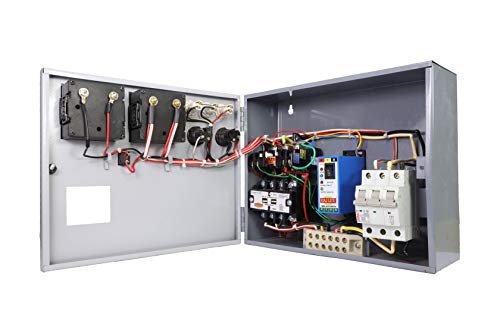
Some sites may include caustic vapor or liquid, as well as temperature extremes. When selecting motors and control components, all of these factors should be taken into account. The combination starter is another form of starter that is widely seen in industry (Figure 1–5). The disconnecting means, fuses or circuit breakers, starting, and control transformer are all housed in the combination starter. To operate the motor, they may additionally feature a series of push buttons or switches installed on the front panel.

Figure 1-5 circuit breaker, disconnect switch,
starting, and control transformer all in one motor starter.
Standards and Codes
The safety of the operator or anybody working close to the equipment is a crucial factor.
OSHA, or the Occupational Safety and Health Act, was created in 1970. OSHA generally requires employers to provide a space free of known risks that might result in severe injuries.
Underwriters Laboratories is another company with significant impact in the electrical industry (UL). Insurance companies founded Underwriters Laboratories in an effort to lower the incidence of fires brought on by electrical equipment. They put equipment through tests to see if it is secure in various scenarios.
A yearly magazine that receives biweekly supplements lists approved equipment.
The National Electrical Code is another body that was mentioned earlier. The National Fire Protection Association includes The NEC® as a member. For the installation of electrical equipment, they develop guidelines and requirements. Unless it is made a law by a local government, the National Electrical Code is not a legal document.
NEMA and IEC are two further groups that have a significant impact on control equipment. Later on in the book, each of these groups will be covered.
Control System Types
The three main categories of motor control systems are manual, semiautomatic, and automated. The characteristic of manual controls is that any change in the state of the control system must be initiated by the operator physically going to the controller’s location. The majority of the time, manual controllers are extremely basic components that attach the motor to the line directly. They might or might not offer low voltage release or overload protection.
Simply attaching a switch in series with a motor will provide manual control (Figure 1–1).
Push buttons, limit switches, pressure switches, and other sensing devices are typically used in semiautomatic control to regulate the functioning of a magnetic contactor or starter. Push buttons and other pilot devices operate the starter’s coil, which is what really connects the motor to the line. This makes it possible to place the real control panel far from the motor or starter. Even if the operator does not need to physically get to the site of the motor or starter to conduct some activities, such as starting and halting, they still need to be initiated. In Figure 1-6, a typical control panel is displayed. Figure 1-7 depicts a schematic and wiring diagram for a start-stop push-button station.

Figure 1-6 A standard push-button control panel.
A schematic diagram depicts components in their electrical order, regardless of physical position.
A wiring diagram is essentially a visual depiction of the control components with connected cables. Although the two circuits in Figure 1-7 appear to be distinct, they are electrically identical.


1-7 Figure A start-stop push-button control has a schematic and a wiring diagram.
Automatic control is similar to semiautomatic control in that pilot sensing sensors are used to drive a magnetic contactor or starter, which operates the motor. However, with automated control, the operator is not required to start certain operations.
Once the control conditions are set, the system will run on its own.
The heating and cooling system present in many houses is an example of an automated control system. Once the thermostat is adjusted to the appropriate temperature, the heating or cooling system runs independently of the house owner. The control circuit incorporates detecting devices that shut down the system automatically in the case of a dangerous condition, such as motor overload, excessive current, no pilot light or ignition in gas heating systems, and so on.
Motor Control Functions
Motor control systems provide several basic roles. The ones listed below are not the only ones, but they are extremely prevalent. This chapter will go through these fundamental functions in greater depth. It is critical to comprehend not just the basic operations of a control system, but also how control components are used to accomplish the required circuit logic.
Starting
One of the primary functions of a motor control circuit is to start the motor. Depending on the circuit’s needs, there are numerous approaches that may be used. Starting across the line is the easiest technique.
This is performed by directly connecting the motor to the power line. However, there may be circumstances in which the motor must begin at a low speed and gradually increase to full speed. This is commonly known as ramping. In other cases, limiting the amount of current or torque during beginning may be essential. Some of these techniques will be covered later in the text.
Stopping
The control system can also be used to halt the motor. The most basic way is to unplug the motor from the power supply and let it coast to a halt. However, some situations may need that the motor be stopped faster quicker or that a brake hold a load when the engine is stopped.
Inching or Jogging
Jogging and inching are techniques for moving a motor with small bursts of power. This is commonly used to reposition a motor or load into a desired position. The distinction between jogging and inching is that jogging is performed by briefly connecting the motor to full line voltage, whereas inching is accomplished by briefly connecting the motor to full line voltage.
Speed Control
Variable speed is required by some control systems.
There are numerous approaches that may be used. Variable frequency control for alternating current motors or adjusting the voltage delivered to the armature and fields of a direct current motor are two of the most frequent methods. Another approach might be to employ a direct current clutch. These strategies will be covered in greater depth later in this work.
Motor and Circuit Protection
One of the most important duties of most control systems is to safeguard both the circuit components and the motor. Fuses and circuit breakers are commonly used for circuit protection, whereas overload relays safeguard the motor. The many forms of overload relays will be covered later.
Surge Protection
Voltage spikes or surges caused by collapsing magnetic fields when power to a relay or contactor coil is switched off are another source of worry in many control circuits. These collapsing magnetic fields can cause hundreds of volt voltage spikes (Figure 1-8). These high voltage surges have the potential to harm electrical components that are connected to the power line.
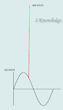
1-8 Figure The voltage spikes caused by collapsing
magnetic fields can reach hundreds of volts.
Voltage spikes are especially dangerous in control systems that use computer-controlled devices like programmable logic controllers and measuring equipment to detect temperature, pressure, and so on.
A metal oxide varistor (MOV) is frequently coupled across alternating current coils (Figure 1–9).

Figure 1-9 A metal oxide varistor (MOV) is used to reduce
voltage spikes on alternating current-connected coils.
Voltage sensitive resistors are metal oxide varistors. They may modify their resistance value in response to the amount of voltage supplied to them. The MOV will have a higher voltage rating than the coil it is linked across. An MOV linked across a coil designed to function at 120 volts, for example, will have a rating of around 140 volts. As long as the voltage supplied to the MOV is less than its voltage rating, it will have an extraordinarily high resistance, often several million ohms. The current flowing through the MOV is known as leakage current, and it is so little that it has no effect on the circuit’s functionality.
If the voltage across the coil exceeds the MOV’s voltage rating, the resistance of the MOV will abruptly shift to an extremely low value, usually in the region of 2 or 3 ohms. This effectively short-circuits the coil and prevents the voltage from rising over the MOV’s voltage rating (Figure 1–10). Metal oxide varistors change resistance values very fast, often between 3 and 10 nanoseconds. When the circuit voltage falls below the MOV’s voltage rating, it will revert to its high resistance state. The MOV dissipates the energy of the voltage surge as heat.

Figures 1-10 The voltage spike is limited
to 140 volts by the metal oxide varistor.
Diodes are used to decrease the voltage spikes produced by direct current coils. The diode is reverse biased to the voltage applied to the coil (see Figure 1–11). During normal operation, the diode inhibits current flow, allowing full circuit current to pass through the coil. When the power is turned off, the magnetic field around the coil decreases, causing a voltage to be induced in the coil. Because the induced voltage has the opposite polarity as the applied voltage (Lenz’s Law), it leads the diode to become forward biased . A silicon diode has a forward voltage drop of around 0.7 volt. This reduces the induced voltage to roughly 0.7 volt. The diode dissipates the energy of the voltage surge as heat.

Figure 1-11 A diode is used to avoid
voltage spikes on direct current-connected coils.
Safety
The most essential duty of any control system is to protect the operator and anybody else who may be in the proximity of the equipment. These safeguards will differ from one machine to the next based on the machine’s specialized function. Many machines include both mechanical and electronic protection.