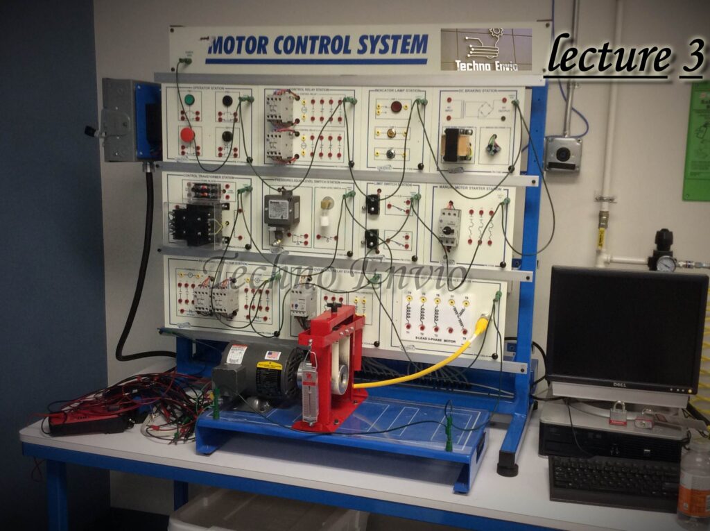
Part 5 Alternating Current Motor Drives: VFDs and Inverter Duty Motors
AC motor drives are critical for controlling speed, torque, and efficiency in industrial automation, HVAC systems, and robotics. With the advent of variable-frequency drives (VFDs) and inverter-compatible motors, engineers can achieve precise control and energy savings. This article explores AC motor drives, VFDs, and inverter-duty motors, complete with equations, practical examples, and mini-project ideas.

1. Alternating Current Motor Drives
An AC motor drive controls an AC motor’s speed, torque, and direction by manipulating applied voltage and frequency. Traditional methods include resistors or pole-changing, but modern drives use electronic controllers.
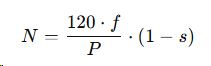
Key Equation – AC Motor Speed:
Where:
-
N = Rotor speed (RPM)
-
F = Supply frequency (Hz)
-
P = Number of poles
-
s = Slip
AC motor drives improve efficiency by adjusting frequency and voltage to match load requirements.
Mini Project Idea:
Simulate an AC motor drive in MATLAB Simulink or Proteus, adjusting frequency to observe motor speed changes.
2. Variable-Frequency Drive (VFD)
A Variable-Frequency Drive (VFD) is an electronic device that controls AC motor speed and torque by varying input frequency and voltage. VFDs are widely used in pumps, conveyors, fans, and compressors.
Basic Components of a VFD:
-
Rectifier: Converts AC to DC
-
DC Link / Bus: Stores energy
-
Inverter: Converts DC back to AC at desired frequency
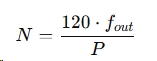
VFD Equation for Speed Control:
Where:
-
= Output frequency from inverter
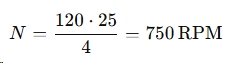
Example:
For a 4-pole motor with a VFD output of 25 Hz:
Advantages of VFDs:
-
Precise speed control
-
Reduced energy consumption
-
Smooth start and stop, reducing mechanical stress
Mini Project Idea:
Use a small AC induction motor with a low-voltage VFD kit. Vary the frequency and measure speed and torque response. Plot frequency vs. RPM.
3. Inverter Duty Motor
An Inverter Duty Motor is designed to handle rapid voltage and frequency changes from a VFD without overheating or insulation damage. Standard AC motors may overheat or fail if connected directly to VFDs.
Key Features:
-
Enhanced insulation for high-frequency switching
-
Suitable for long-term operation with VFDs
-
Reduced bearing currents and vibration
Practical Tip:
Always pair VFDs with inverter-duty rated motors in industrial applications to ensure longevity and reliability.
Mini Project Idea:
Compare two small AC motors—standard vs inverter-duty—operated by a VFD. Measure temperature rise and vibration at varying frequencies to see differences in performance.
Applications of AC Motor Drives and VFDs
-
HVAC systems: Fans, pumps, and compressors
-
Conveyor systems: Adjustable speed for production lines
-
Pumps and compressors: Energy-efficient flow control
-
Industrial automation: Robotics and CNC machines
Practical Tip:
Implementing VFDs in industrial systems can reduce energy consumption by 20–50% compared to fixed-speed motors.
Conclusion
AC motor drives, VFDs, and inverter-duty motors are essential tools for modern industrial automation. Understanding their operation principles, equations, and practical applications ensures efficient motor control and energy savings.
By combining theory, hands-on experiments, and mini-projects, engineers and students can gain practical skills for designing, testing, and optimizing AC motor systems.
Part 6 Motor Selection: How to Choose the Right Motor for Your Application
Selecting the correct motor is essential for reliable, efficient, and safe operation in industrial, commercial, and residential applications. Choosing the wrong motor can lead to overheating, inefficiency, or mechanical failure. This article provides a detailed guide on motor selection criteria, ratings, and specifications, with equations, examples, and practical considerations.
1. Mechanical Power Rating
The mechanical power rating of a motor indicates the maximum power it can deliver at the shaft. It is typically expressed in watts (W) or horsepower (HP).
Equation for Mechanical Power:
Where:
-
= Mechanical power (W)
-
T = Torque (Nm)
-
= Angular speed (rad/s)
Example:
A motor delivering 10 Nm torque at 150 rad/s:
2. Current Rating
The current rating determines the electrical load a motor draws. Ensuring the motor current is compatible with the power supply is critical to avoid overheating or tripping circuit breakers.
Equation:
Where:
-
I = Current (A)
-
P = Motor power (W)
-
V = Supply voltage (V)
-
η= Efficiency
-
PF = Power factor
Mini Project Idea:
Measure the current of a small AC motor using a clamp meter at various loads to understand real-world power consumption.
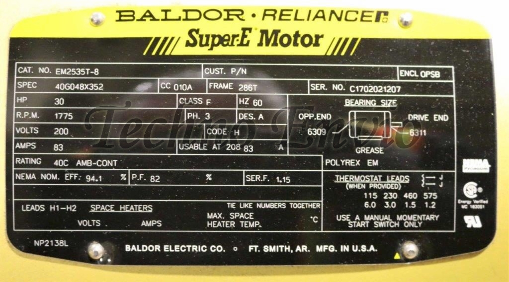
3. Code Letter (Locked-Rotor kVA Code)
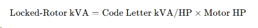
The Motor Code Letter is a standardized designation found on NEMA motor nameplates. It indicates the amount of current the motor draws during starting, expressed as locked-rotor kVA per horsepower (kVA/HP).
Understanding the code letter is essential for:
-
Proper electrical system design
-
Correct sizing of circuit breakers and conductors
-
Avoiding excessive voltage drop during motor starting
What the Code Letter Represents
When a motor starts, the rotor is stationary (locked rotor), and the motor draws inrush current that can be 5 to 8 times the full-load current.
Instead of listing actual starting current, NEMA uses a letter code to represent a range of starting kVA per HP.
Code letters classify motors by full-load speed range, making it easier to select a motor for a given application. For example:
-
A: 2800–3150 RPM
-
B: 2310–2800 RPM
-
C: 1890–2310 RPM
NEMA Motor Code Letter Table
| Code Letter | Locked-Rotor kVA per HP |
|---|---|
| A | 0 – 3.14 |
| B | 3.15 – 3.54 |
| C | 3.55 – 3.99 |
| D | 4.00 – 4.49 |
| E | 4.50 – 4.99 |
| F | 5.00 – 5.59 |
| G | 5.60 – 6.29 |
| H | 6.30 – 7.09 |
| J | 7.10 – 7.99 |
| K | 8.00 – 8.99 |
| L | 9.00 – 9.99 |
| M | 10.00 – 11.19 |
| N | 11.20 – 12.49 |
| P | 12.50 – 13.99 |
| R | 14.00 – 15.99 |
| S | 16.00 – 17.99 |
| T | 18.00 – 19.99 |
| U | 20.00 – 22.39 |
| V | 22.40 and up |
How to Calculate Starting Current Using Code Letter
Example Calculation
Motor:
-
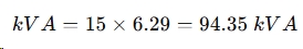
Power: 15 HP
-
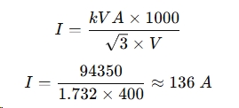
Voltage: 400 V
-
Code Letter: G
-
kVA/HP (max): 6.29
Step 1: Calculate Locked-Rotor kVA
Step 2: Calculate Starting Current
This current must be considered when selecting:
-
Circuit breakers
-
Contactors
-
Cable sizes
Motor Starting Method Selection
| Code Letter | Recommended Starting |
|---|---|
| A–C | Direct-On-Line (DOL) |
| D–H | Soft Starter |
| J and above | VFD or Reduced-Voltage Start |
4. Design Letter of Motor
Design letters (e.g., Design A, B, C, D) indicate torque-speed characteristics:
-
Design A: Standard torque, general-purpose
-
Design B: High starting torque, heavy-duty loads
-
Design C: Special high torque for specific applications
-
Design D: Very high torque for cranes and hoists
Example:
A conveyor belt requiring high starting torque would use a Design B motor.
5. Efficiency of Motor
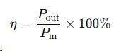
Motor efficiency (η\eta) is the ratio of mechanical output power to electrical input power:
Energy-Efficient Motors reduce operational costs and environmental impact. Motors rated IE3 or IE4 are standard for industrial applications.
6. Frame Size
The frame size determines the mounting and physical dimensions of the motor. It ensures compatibility with mechanical couplings, gearboxes, or equipment.
Mini Project Idea:
Compare motors of different frame sizes and measure their torque per unit weight to understand efficiency and mechanical design considerations.
7. Frequency
Frequency (Hz) affects synchronous speed:
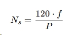
Where:
-
= Synchronous speed (RPM)
-
F = Supply frequency (Hz)
-
P = Number of poles
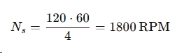
Example:
A 4-pole motor on a 60 Hz supply:
8. Full-Load Speed
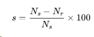
Full-load speed is the rotational speed under rated load. It is slightly lower than synchronous speed due to slip in induction motors.
Slip Calculation:
9. Load Requirements
Understanding load type is essential:
-
Constant load: Standard motor is sufficient
-
Variable load: Consider torque-speed characteristics and VFD control
-
High starting torque load: Choose series or design B/D motors
1. Constant Torque Loads
Torque remains constant regardless of speed.
Examples:
-
Conveyors
-
Elevators
-
Positive displacement pumps
-
Mixers
Torque equation:
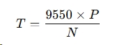
Where:
-
T = Torque (Nm)
-
P = Power (kW)
-
N = Speed (RPM)
Motors for constant torque loads must deliver full rated torque at all speeds.
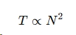
2.Variable Torque Loads
Torque varies with the square of speed.
Examples:
-
Fans
-
Centrifugal pumps
-
Blowers
These loads benefit greatly from VFDs due to energy savings
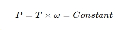
3. Constant Power Loads
Torque decreases as speed increases.
Examples:
-
Machine tools
-
Winders
-
Spindles
10. Motor Temperature Ratings
Motor insulation classes (B, F, H, etc.) indicate maximum allowable operating temperature. Selecting an appropriate insulation ensures long life and safe operation.
Insulation Classes
| Class | Max Temperature (°C) |
|---|---|
| A | 105 |
| B | 130 |
| F | 155 |
| H | 180 |
Rule of Thumb:
Every 10°C rise above rated temperature reduces insulation life by 50%.
Temperature Rise
Motor nameplates specify temperature rise, not total temperature.
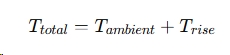
Example:
Ambient = 40°C
Temperature rise = 80°C
Total = 120°C → Class B acceptable
11. Duty Cycle
Duty cycle defines how long a motor can operate before rest is required:
-
Continuous (S1): Operates indefinitely at rated load
-
Intermittent (S2–S6): Operates for short periods
Common Duty Types (IEC Standard):
12. Torque
Torque determines load-moving ability. Important for applications like conveyors, pumps, or cranes.
Torque Equation:
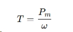
Example:
Motor with 2 kW output at 150 rad/s:
13. Motor Enclosures
Motor enclosures protect against dust, moisture, and mechanical damage:
-
TEFC (Totally Enclosed Fan Cooled)
-
ODP (Open Drip Proof)
-
Explosion-proof
14. Metric Motors
Metric motors provide standardized dimensions for international compatibility, making maintenance and replacement easier.
Mini Project Idea:
Select two motors for a small conveyor: one standard and one metric. Compare torque, efficiency, and mounting ease.
Conclusion
Motor selection involves considering mechanical power, torque, current, speed, efficiency, frame size, duty cycle, and environmental conditions. By applying the equations and selection criteria described above, engineers and hobbyists can choose the optimal motor for their application, ensuring reliability, energy efficiency, and long-term performance.