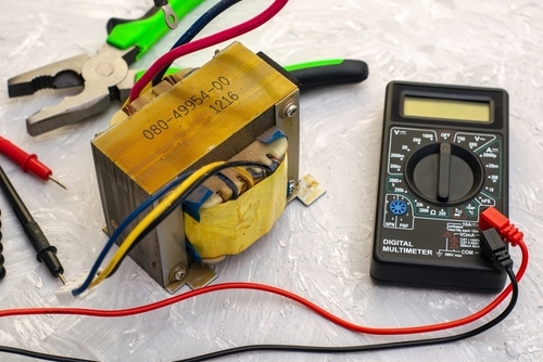
Testing a Transformer
Finding Important Transformer Data
1.Examine the transformer with your eyes.

Overheating, which induces the internal wire of the transformer to get hot, is a common cause of transformer failure. The transformer and its surroundings often physically distort as a result of this.
If there are bulges or what seem to be burn marks on the transformer’s outside, do not test the transformer. Replace it, on the other hand.
2.schematic diagram of a transformer

There should be adequate labelling on the transformer’s wiring. Usually, it is best to obtain a schematic of the circuit that contains the transformer in order to determine how the transformer is connected.
Either the product details or the circuit manufacturer’s website will have the circuit schematic available.
3.Determine the transformer’s inputs and outputs.

The transformer’s primary will be connected to the first electrical circuit. Its power source is this. The second circuit that the transformer supplies power to is connected to the secondary, or output, of the transformer.
The voltage supplied to the primary should be marked on the schematic and the transformer.
Labelling the secondary voltage using the same terminology as the main voltage is appropriate.
4.Find out how the output is filtered.

Diodes and capacitors are frequently attached to the secondary of the transformer in order to convert the AC power coming from the output to DC power. This details won’t be on the transformer label.
The schematic often contains information about output filtering and transformer conversion.
Check the label to see if the transformer is DC or AC, or wherever the voltage is stated.
Using a Digital Multimeter to Testing a Transformer
1.Measure the circuit voltages

Switch off the circuit’s power supply. As necessary, remove panels and covers to get access to the transformer circuits. To measure voltage, get a digital multimeter. Hardware stores, hobby shops, and electrical supply stores carry digital multimeters.
Connect the leads of your digital multimeter to the input lines to make sure the transformer’s main is not shorted. The identical protocol will be applied to the testing of the transformer secondary.
2.Check the transformer’s input.

Attach the electricity to the circuits. Put the digital multimeter in AC mode and use it to measure the primary transformer. The transformer or the circuitry that powers the primary may be malfunctioning if the measurement is less than 80% of the expected voltage. Remove the transformer from the input circuit in this instance. Check the input by using your digital multimeter instead. If the input power increases to the anticipated amount, there is a problem with the transformer’s primary.
The input circuitry, not the transformer, is at fault if the input power does not increase to the appropriate amount.
The input and output of the transformer can have labels such as “input” and “output,” or the input can just be a pigtail that is white and black.
3.Check the transformer’s secondary output.

If the secondary circuitry is not performing any filtering or shaping, read its output using the DMM’s AC mode. If there is, utilised the DMM’s DC scale.
If the expected voltage on the secondary is not there, then the transformer or a filtering or shaping component is faulty. Separately, test the filtering and shaping components.
If the filtering and shaping components are tested and show no difficulties, the transformer is defective.
How to fix or repair the Transformer
1.Determine the reason of the problem.

A failure of another kind elsewhere in the electrical circuit often leads to transformer failure. Transformers seldom burn out on their own and have long lifespans.
2.Take note of the new transformers.

If there is another problem in your circuit that is causing the transformer to short out, there’s a chance that it will burn out again. After the transformer is replaced, check it to make sure this doesn’t happen. If it does, additional testing will need to be conducted.
An overcharged transformer will often make noises like snapping and crackling. If you hear noises similar to these, cut off the transformer’s power to prevent burnout.
3.If required, check the status of the external fuses.

It’s possible that the line going up to your transformer has no fuses if it has an internal fuse. If not, the power supply line of the transformer has to have fuses fitted in it. Verify if they are in perfect working condition and replace any that aren’t.
The presence of fuse darkness, melting, and distortion are indications of fuse damage. Just remove them and put the new ones in.
In certain situations, it may be challenging to determine whether a fuse is in great condition. With one lead on each end, connect your digital multimeter to the fuse. Everything is good if the fuse is able to conduct current.
4.Check your secondary winding.

There is a chance that the secondary of your transformer is shorting out due to excessive current demand. A multi-tap transformer’s secondary is most likely shorted if you get the reading “OL” from it.
Apply a circuit to the secondary and check the secondary lines with your digital multimeter. An excessive amount of power is being consumed by the circuit if the value is greater than the transformer’s amperage rating.
On many common transformers, three-amp fuses are utilized. Your transformer fuse’s amperage rating is indicated in the circuit diagram in addition to perhaps being marked on the transformer.
5.To find the source of the failure, remove all inputs and outputs.

With linear fuses, you have a single input and a single output. Either the input or the output circuit is the source of the issue in this case. To identify which part of the whole circuit is causing the short, remove each input and output from the transformer individually if using more complex fuses.

