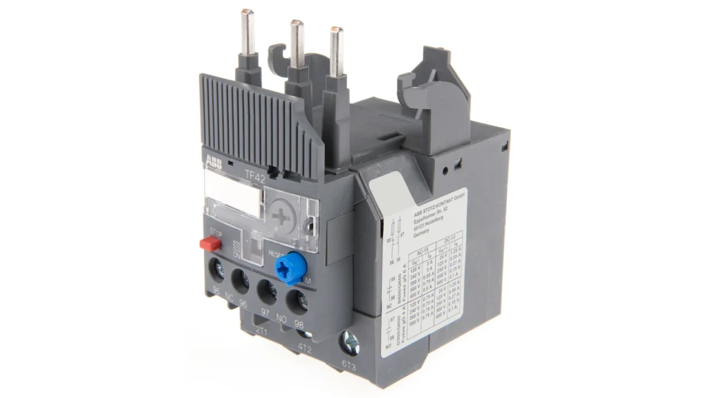
Overload Relay is not the same as fuses or circuit breakers. Fuses and circuit breakers are used to safeguard a circuit from a direct ground or a short circuit. Overload Relay is used to prevent the motor from overheating. the motor is connected to a circuit that is protected by a 20 amp circuit breaker, as shown in Figure 4-1. Assume the motor becomes overworked and draws 15 amps of current. The motor is drawing 150% of its maximum load current. This great of an overload will cause the motor to overheat and ruin the windings. However, because the current is just 15 amps, the 20 amp circuit breaker will not trip to safeguard the motor.
Overload relays are intended to open the circuit when the current reaches 115% to 125% of the full load current of the motor. The overload setting is determined by the qualities of the motor to be protected.
Overload relay
Overload Relay Properties
To safeguard a motor, all overload relays must have the following characteristics:
1. They must be able to detect motor current. Some overload relays do this by transforming motor current into a corresponding quantity of heat, while others detect motor current by measuring the intensity of a magnetic field.
2. There must be some kind of time delay. When starting, motors generally consume 300% to 800% of their full load current. The locked rotor current is the beginning current of a motor. Because overload relays are typically configured to trip at 115% to 125% of full load motor current, if the overload relay tripped instantly, the motor would never start.
3. They are separated into two sections: the current sensing part and the contact section.
The current detecting portion is linked in series with the motor and detects motor current. This portion is usually linked to voltages ranging from 120 to 600 volts. The contact section is a control circuit component that functions at the control circuit voltage. Control circuit voltages typically vary from 24 to 120 volts, while some controllers run on 240 or 480 volt lines.
Fuses with Two Elements
Some fuses are designed to give both short circuit protection and overload protection. These are known as dual element time delay fuses. They are divided into two parts (Figure 4–2). The first has a fuse connection that is meant to open fast in the event of a high quantity of surplus current. This safeguards the circuit against short circuits and direct grounding. The second portion moves more slowly; it has a solder link attached to a spring. The solder is a carefully regulated alloy that melts at a certain temperature.
If the motor current becomes too high, the solder melts and the spring pulls the connection apart. The requisite time delay is obtained due to the time required for the solder to melt even under high current.
If the motor current returns to normal after starting, the solder will not become enough hot to melt.
Figure 4-2 Time delay fuse with dual elements
Thermal Overload Relay
Overload relays are classified into two types: thermal and magnetic. Thermal overloads work by attaching a heater to the motor in sequence. The quantity of heat produced is proportional to the motor current. Thermal overloads are classified into two types: solder melting or solder pot overloads and bimetal strip overloads. Thermal overload relays are sensitive to ambient (surrounding air) temperature because they function on the basis of heat.
They will travel quicker in a warm environment than in a cool environment.
Type of Solder Melting
Solder melting overloads are also known as solder pot overloads. A brass shaft is inserted within a brass tube to generate this sort of overload. One end of the brass shaft is linked to an a serrated wheel. The brass shaft is physically attached to the brass tube by a particular alloy solder that melts at a very specified temperature (Figure 4–3). The serrated wheel closes a set of spring-loaded contacts (Figure 4–4). An electric heater is positioned near or around the brass tube. The heater and the motor are linked in series. The heater generates heat as a result of the motor current.
Figure 4-3 shows Construction of a typical solder pot overload.
The serrated wheel closes a set of spring-loaded contacts (Figure 4–4). An electric heater is positioned near or around the brass tube. The heater and the motor are linked in series. The heater generates heat as a result of the motor current.
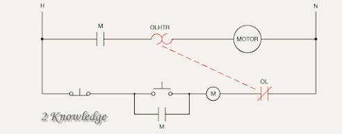
Figure 4-4 thermal overload relay for melting alloy. If heat melts the solder, a spring forces the connections open, allowing the serrated wheel to spin freely. Keep in mind the electrical symbols for the heating element and the usually closed overload contact.
The solder will melt if the current is high enough and lasts long enough, allowing the brass shaft to revolve within the tube and opening the contact. The time delay for this overload relay is caused by the fact that it takes some time before the solder can get hot enough to melt. The solder will melt more quickly and the contacts will open more quickly with a significant overload than with a minor overload current.
Manufacturers build their solder melting type overload heaters differently, however they all operate on the same principle.
In Figure 4-5, sections A and B, two distinct kinds of melting alloy heater assemblies are depicted.
Figure 4-6 depicts a common melting alloy type overload relay. It takes two to three minutes for the overload relay to cool down after tripping, and then it may be reset.
This cooling period is required to allow the solder to harden once it has cooled after melting.
By switching out the heater, the trip current setting may be altered. Manufacturers offer charts that specify the size of heater that has to be placed for various motor current levels. Use the chart that is appropriate for the specific type of overload relay. Not all charts display the data in the same way. When choosing heater sizes, be careful to read the directions that come with the chart. In Figure 4-7, a typical overload heater chart is displayed.
Bimetal Strip Overload Relay
The bimetal strip overload is the second variety of thermal overload relay. Similar to the melting alloy type, it works on the premise of transforming a certain quantity of motor current into heat. The distinction is that a bimetal strip is bent or warped using heat. By joining two kinds of metal that grow at various rates, a bimetal strip is created (Figure 4–8).
Because the metals expand at different rates, the strip will warp or bend as the temperature changes (Figure 4–9).
The following factors affect the amount of warp:
1. The kind of metals that were utilized to make the bimetal strip.
2. The variation in temperature between the strip’s two ends.
3. The strip’s length.
The bimetal strip is heated by the overload heater when motor current passes over it. The bimetal strip warps as a result of the heat. A set of contacts will open if the bimetal strip heats up enough (Figure 4-10). Approximately two minutes must pass after the overload contact opens in order for the bimetal strip to cool down and return to the proper position so that the contacts may be closed again. The length of time needed for the bimetal strip to warp just enough to open the normally closed contact is the time delay factor for this overload relay. A significant overload current will speed up the warping and contact opening of the bimetal strip.
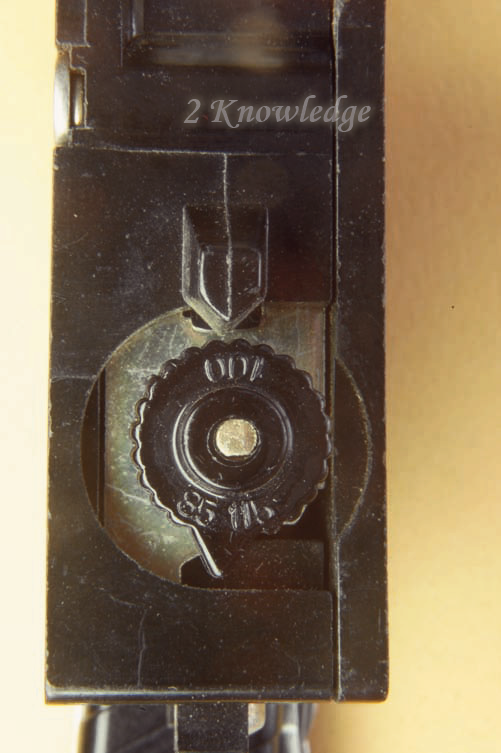
The majority of bimetal strip type overload relays have a few properties that solder melting type overload relays do not. The trip range may often be changed by rotating a knob, as seen in Figure 4-10. By turning this knob, you may change how much the bimetal strip must deform before connections open. With this modification, the sensitivity may be altered in response to variations in the outside air’s temperature. The overload runs at its full load current rating, as indicated by the size of the fitted overload heater, if the knob is set to 100% (Figure 4-11). This setting can be too high to safeguard the engine during the chilly winter months. In cold weather, the knob may be set to run at any position between 100% and 85% of the motor’s full load current. The motor may “nuisance trip” during the hot summer months because of the high outside temperature. The adjustment knob allows the overload relay to be set between 100% and 115% of motor full load current for hot situations.
Figure 4-11 Between 85% and 115% of the heater
rating can be changed using an adjustment knob to the present level.
There are various bimetal strip type overload relays that may be adjusted for either a manual or automated reset, which is another distinction from the solder melting kind. This configuration is made possible by a spring on the side of the overload relay (Figure 4–12). Pushing the reset lever is required to manually reset the contacts once they have been set to the manual position. Probably the most typical setting for an overload relay is this one. After the bimetal strip has cooled down sufficiently, the contacts will automatically shut if the overload relay has been set up for automatic reset.
If it may result in a rapid restart of a machine, this can be a safety risk.
Figure 4-12 Numerous bimetal strip type overload
relays include manual or automated reset adjustments.
When there is no risk of injury or equipment damage from the rapid closure of the overload connections, overload relays should only be programmed to automatically reset.
Three Phases Overloads
The overload relays that have been mentioned thus far are designed to monitor the current flowing via a single conductor that powers a motor (Figure 4–13).
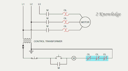
The protection of a single-phase or direct current motor is one use for this kind of overload relay. To safeguard a single-phase or direct current motor that runs on 120 or 240 volts, the NEC simply calls for one overload sensor device. However, each three-phase line of a three-phase motor must incorporate an overload sensor (heaters or magnetic coils). In certain motor starters, three single-overload relays are used to independently sense the current in each of the three-phase lines (Figure 4–14).
motor is sensed by three single-phase overload relays.
Following this, each overload relay’s usually closed contact is wired in series as illustrated in Figure 4-15. The power to the starting coil is cut off and the motor is unplugged from the power line if any one of the relays opens its usually closed contact.
Figure 4-15 The usually closed contacts of each overload relay are linked in series when three single-phase overload relays are used to safeguard a three-phase motor.
Additionally, three overload heaters and one pair of usually closed contacts can be found in overload relays, as shown in Figure 4-16.
Three-phase motors are often protected by these relays. Despite the fact that there is only one set of typically closed connections, if any one of the three heaters experiences an overload, the contacts open, disconnecting the motor starter’s coil (Figure 4–17).
Figure 4-17 A three-phase overload relay has one set
of normally closed contacts but three overload heaters.
Magnetic Overload Relays
Overload relays of the magnetic kind work by detecting how strong the magnetic field created by the current flowing to the motor is. The fact that magnetic overload relays are not temperature-sensitive is their main distinction from thermal overload relays. Overload relays of the magnetic type are frequently utilized in locations with abrupt variations in the ambient temperature. There are two main categories of magnetic overload relays: electronic and dashpot.
Electronic overload relays
A current transformer is used by electronic overload relays to measure the motor current. A toroid transformer’s core is traversed by the cable that powers the motor (Figure 4–18). The alternating magnetic field around the wire produces a voltage into the toroid transformer as current passes through it. The conductor’s current flow determines how much induced voltage will be present.
Most clamp-on type ammeters operate on the same fundamental concept.
Figure 4-18 Electronic overloads measure the intensity
of a magnetic field to detect motor current.
Through a linked electrical interface, the voltage generated into the toroid transformer is transferred, causing a temporal delay that enables the motor to turn on.
The amount of full load motor current, maximum and lowest voltage levels, percentage of overload, and other parameters may all be programmed into many electronic type overload relays. Figure 4-19 depicts an electronic three-phase overload relay.
field, electronic overloads detect motor current.
Dashpot Overload Relays
The component that creates the time delay that enables the motor to start gives dashpot overload relays their name. A piston, a shaft, and a container make up a dashpot timer (Figure 4–20).
mostly of a piston, a shaft, and a container.
The piston is put into the container, which is then filled with dashpot oil, an unique kind of oil (Figure 4–21). Dashpot oil keeps its viscosity steady across a broad temperature range. One of the elements that affects how much time the timer delays is the kind and viscosity of the oil utilized.
The other factor is the position of the orifice holes in the piston (Figure 4–22). As the piston rises through the oil, the orifice holes allow the oil to flow through it. The orifice hole opening may be adjusted by moving a sliding valve on the piston.
A coil in the dashpot overload relay is linked in series with the motor (Figure 4–23). As current runs through the coil, a magnetic field forms around it. The magnetic field strength is proportional to the motor current. This magnetic field pulls the dashpot timer shaft into the coil. The piston must displace the oil in the container, which slows the shaft’s movement.
If the motor is running properly, the current in the motor will decrease to a safe level before the shaft is pushed deep enough into the coil to open the normally closed contact (Figure 4-24).
However, if the motor is overloaded, the magnetic field will be strong enough to continue dragging the shaft into the coil until the overload contact is opened. When the engine is turned off, the magnetic field collapses and the piston falls to the bottom of the container. When the motor current is turned off, check valves allow the piston to nearly instantaneously return to the bottom of the container.
Dashpot overloads often have some way for adjusting the relay for varied full load current values. The shaft is attached to a threaded rod in order to accomplish this adjustment (Figure 4–25).
This allows for the shaft to be extended or shortened within the coil. The longer the shaft, the less current is necessary to pull it into the coil far enough to open the contacts. A nameplate on the coil lists the various current values for a certain overload relay (Figure 4–26).
The shaft is adjusted by sliding it until the line indicating the required current is flush with the top of the dashpot container (Figure 4–27). Figure 4-28 shows a dashpot overload relay.
a line on the shaft that is flush with the top of the dashpot container.
Figure 4-28 shows a dashpot overload relay.
Figure 4–28 Shows Dashpot overload relay.
Overload Contacts
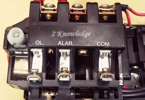
While all overload relays include a set of typically closed contacts, some manufacturers additionally include a set of normally open contacts. These two sets of contacts might be a single-pole double-throw switch or two independent contacts. A common terminal (C), a normally closed terminal (NC), and a normally open terminal (NO) will be included in the single-pole double-throw switch layout (Figure 4–29). There are various reasons why you should include the regularly open set of contacts.
Fig. 4-29 Overload relay has two contacts, one ordinarily closed and one normally open. The ordinarily closed contact is denoted as OL, whereas the normally open contact is denoted as ALAR. (The common contact is denoted by the letter COM.)
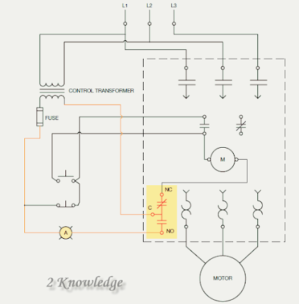
The usually closed part of the starter illustrated in Figure 4-30 is used to disconnect the motor starter in the case of an overload, while the normally open section is used to turn on an indicator light to notify an operator that the overload has tripped.
Fig. 4-30 The overload relay has a single-pole double-throw contact configuration. The usually closed part (NC) safeguards the motor in the case of an overload condition, while the ordinarily open section (NO) illuminates an indication lamp to notify the operator that the motor has tripped due to overload.
Figure 4-31 depicts an overload relay with two independent sets of contacts, one generally open and the other normally closed. Another popular application for an overload relay’s normally open group of contacts is to supply an input signal to a programmable logic controller (PLC).
If the overload is tripped, the typically closed set of contacts opens, disconnecting the starting coil from the line. The typically open set of contacts will shut, sending a signal to the PLC’s input (Figure 4–32). To separate the PLC and the motor starter, two interposing relays, CR1 and CR2, are employed. This is frequently done for reasons of safety.
The control relays prohibit multiple power sources from accessing the starter or PLC. It should be noted that the starter and PLC each have their own power supply. If the power to the starting was withdrawn during servicing or repair, it might cause an injury if the power from the PLC was linked to any portion of the starter.
Figure 4–32 The typically open connections
send a signal to the programmable logic controller’s input.
Protecting Large Horsepower Motors
Large horsepower motors sometimes have current needs of several hundred amps, making overload heater sizing challenging. In this circumstance, current transformers are commonly utilized to minimize the amount of current to the overload heaters (Figure 4-33).
Figure 4-33 depicts current transformers with ratios of 150:5. This implies that if the secondary terminals are shorted together and 150 amps of current flow through the primary, which is the line connected to the motor, the transformer secondary will create a current of 5 amps.
The secondaries of the current transformers are linked to the overload heaters to safeguard the motor (Figure 4–34).
Assume the entire load current of the motor linked to the current transformers in Figure 4-34 is 136 amps. When 136 amperes pass through the primary, current transformers with a ratio of 150:5 create a secondary current of 4.533 amperes.
150/5 = 136/X
150X = 680
X = 680/150
X = 4.533
Overload heaters would be appropriate for a motor with a full load current of 4.533 amps.
Questions for Review
1. All overload relays are divided into two sections. What are these two sections?
2. What two factors determine the time setting for a dashpot timer?

