Robotic Gripper Construction
Robotic gripper Manufacturing processes in all disciplines are getting increasingly automated as technology advances. With growing productivity demands and recent advancements in cobot programming ease, industrial robots and cobots are becoming a reality in many production areas. Regardless of the task at hand, all robots require an end effector to complete their mission. These end effectors are utilized in a variety of applications, including welding, cutting, spray painting, pick-and-place, inspection, assembly, and 3D printing. This study focuses solely on grasping and clamping mechanisms, sometimes known as grippers. All of these grippers must be able to handle a wide range of objects with varying shapes, dimensions, and weights.
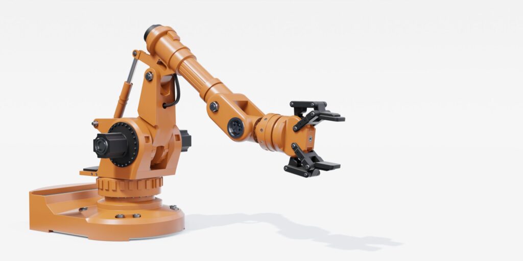
Prehension mechanisms are complicated mechatronic structures utilised by industrial robots to conduct clamping operations on parts in order to handle, transport, or assemble parts within a robotic technological process, and are located at the end of the robotic arm, as shown in Figure 1.
Fig 1 The main components of an industrial robot.
The capacity to grip and operate a range of items has been the driving force behind robot growth.
Various grippers have been created and used in many automatic applications because to the enormous number of requirements, varying workpieces, and the demand for a well-adapted and dependable grasping mechanism. Prehension mechanisms are classified into distinct groups based on various characteristics. These criteria include actuation type, grip modes, number of jaws/fingers, and so forth.
Another difficulty in grasping designs is the inertia forces caused by the fast movement of the robot arm. These inertial forces increase power consumption and make it more difficult to halt the system at exact points.
To reduce these impacts, the gripper system should be compact or made of diverse materials to save weight.
Changing the material used in gripper construction is one of the most simple ways to save weight. For this objective, a composite material was employed and tested in this study for the building of the newly created gripper. Additive technology was employed to make the production process easier.
Stereolithography (SLA), Selective Laser Sintering (SLS), PolyJet, Digital Light Process (DLP), Multi Jet Fusion (MJF), Fused Deposition Modelling (FDM), Direct Metal Laser Sintering (DMLS), Electron Beam Melting (EBM), and other 3D-printing technologies can print with a wide range of materials.
The fundamental idea of 3D printing/additive technologies stays the same across all printing processes, namely the layer-by-layer building of the part. This technology is increasingly being utilised for the fabrication of one-of-a-kind parts as well as series production of parts in a variety of industries, including agricultural, automotive, aerospace, and medical.
2. Materials and Procedures
2.1. Innovative Robot Gripper Solution
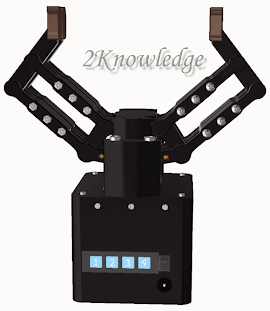
The authors suggest a novel gripper design in this study, which is based on a confidential patent application. The key advantage of the new suggested design is its high level of configurability, with the gripper capable of grabbing/clamping, holding, and manipulating a wide range of parts of various sizes and shapes from the inside or outside. Figure 2 depicts the 3D model of this design. There are several positive answers available. This is because the pieces to be handled have complicated forms. Starting with a technological solution, we attempted to combine multiple solutions into one. This was the starting point for developing this solution.
The gripping system was electronically operated and used a four-jaw/finger parallel open-close motion, resulting in a wider area of contact between the pieces and the system.
Figure 2: The authors’ suggested gripper design.
This gripper is distinguished by its capacity to convert from a four-finger mechanism to a two-finger mechanism by including a secondary electric motor for the folding action of the jaws, as illustrated in Figure 3.
Figure 3 shows the two-jaw finger configuration on the right and the four jaw fingers on the left when the fingers are folded.
Figure 4 depicts the mechanism’s functioning principle, which includes the two electric motors found within the system. The primary motor (labelled 1 in Figure 4) is responsible for opening/unclamping and closing/clamping the jaw fingers, ensuring that the pieces are grasped.
Figure 5, a section view of the system, depicts a thorough view of the concept. A pinion-rack mechanism controls the movement of the fingers.
Figure 4: The gripper’s electrical drive (1—main electric motor, 2—second electric motor).
Figure 5 depicts a section view of the mechanism.
The second electric motor (labelled 2 in Figure 4) converts a four-finger grasp to a two-finger grip and vice versa. This motor moves a rod with a gear segment on it, which interacts with a gear segment positioned on the bottom section of the jaw and may directly operate the jaw.
For the current gripper design, the maximum apart that can be handled is 150 mm. When open and in a 4-finger configuration, the gripper measures 250 mm in width by 250 mm in length (or 110 250 in a 2-finger configuration); and 300 mm in height when the fingers are closed or 255 mm when open.
2.2. 3D-Printing Techniques
To create the actual model, additive manufacturing, or 3D printing, was employed. FDM was the one employed in this study. An FDM 3D printer operates by depositing molten filament material layer by layer on a build platform until the pieces are complete. FDM converts digital design files that are put onto the machine into physical dimensions. Polymers like as ABS, PLA, PETG, and PEI are used in FDM, and the machine feeds them as wires via a heated nozzle [16]. Figure 6 depicts the printing head principle for this form of 3D printing.
Figure 6 depicts the print head’s operation utilizing the FDM technology.
2.3. Materials for Carbon Fiber
The Robotic 3D printers may employ unusual materials such composite materials in addition to the components mentioned above. PET CF15, a polyethylene terephthalate reinforced with 15% carbon fiber, is the material utilized for testing.
Studies have been done on the composite materials’ printability while employing additive manufacturing.
The following are the primary types of fiber-reinforced composites:
- Composites with a polymer matrix: These are often thermoplastic or thermoset resins (polyimide, epoxy, or polyester) reinforced with ceramic monocrystals (or, more recently, metal fibers) or carbon, glass, boron, or aramid fibers (Kevlar). They are particularly useful in situations where the operating temperature is low (the maximum temperature of thermoplastics produced by injection is 400 °C).
- Metal- matrix composites: These are usually based on alloys of aluminum, magnesium, titanium, or copper, with the addition of carbon (graphite), boron, or ceramic (alumina or silicon carbide) fibers. The melting or softening point level of the matrix material sets a restriction on the working temperature, which is typically no more than 800 °C. The high specific weight, which causes the final assembly to become more enormous, is a drawback.
- Composites with a ceramic matrix: Designed for applications requiring very high operating temperatures (above 1000 °C), these composites’ most common basic materials are glass, silicon carbide (SiC), and alumina (Al2O3). They also frequently use ceramic reinforcing fibers, which are typically discontinuous, very short fibers.
- “Carbon-carbon” composites: Made of graphite or carbon matrices, they are reinforced with graphite fibers or fabrics. Although they are highly costly, “carbon-carbon” composites are superior to other materials because of their low density, low coefficient of thermal expansion, and ability to withstand temperatures as high as 3000 °C. The most widely used fiber-reinforced composite materials are Kevlar, carbon fiber, and glass fiber.
The simultaneous application of two criteria—the complimentary material’s geometrical peculiarities and its orientation inside the matrix—provides the basis for yet another, more comprehensive categorization of composite materials.
Based on an analysis of Figure 7, the material utilized in this paper is Fiber-reinforcement → Composite material → Short → Random.
Figure 7: Composite material classification based on reinforcement and matrix type.
2.4. Testing Probes
Different materials were used to create 3D-printed tensile test specimens for testing (Figure 8).
Figure 8: Specimen types and size utilised in own research in accordance with standards.
Standard D638-14 was used to create the tensile specimens and testing [24]. Figure 8 displays a variety of specimen sizes and kinds. It is important to mention that type IV samples were utilised in this study. The measurements on the sketch are denoted by letters since the thickness of the specimen might cause the dimensions to change depending on the type of specimen. The first row of the table shows the example thicknesses, and the standard measurements that correspond to the letters in the picture may be found there as well.
After determining the specimen dimensions, the following step is to set up certain settings for the 3D printer. Three distinct parameter types were examined, each having two values:
- – 60% of the area is filled in (Figure 9);
Figure 9: A 3D-printed specimen with 60% infill.
Figure 10: A 3D-printed specimen with a 100% infill percentage.
Figure 11: A 3D-printed specimen with a 45° raster angle.
- 0.33 mm (as seen in Figure 12);
Figure 12: A Robotic 3D-printed specimen with a 90° raster angle.
– The raster angle:
Figure 13: A Robotic 3D-printed specimen with a layer thickness of 0.17 mm.
Figure 14: A Robotic 3D-printed specimen with a layer thickness of 0.33 mm.
Using these values, a factorial experiment with two levels and three factors, particularly 23, yielded eight potential combinations, as shown in Table 1.
Combinations of printing settings are shown in Table 1.
For a more definitive conclusion, three duplicates of each of these eight types of specimens were prepared. As a result, 24 carbon fiber reinforcement PETG specimens were manufactured.
In addition, for a comparison with traditional Robotic 3D printing materials, PLA and ABS P430 materials with identical printing qualities were utilised, yielding a total of 72 specimens to test.
These are the settings we examined, although there are several articles that combine different printing parameters or processes with different types of materials to optimize component strength.
To establish the force-displacement curve, a traction testing equipment (Lloyd Instruments LRX Plus) was utilized to test the specimen. To fulfil the test standard, the distance between the traction device’s two grippers was set to 65 mm, and the test speed was set to 5 mm/min at room temperature.
The equipment was linked to a computer, which collected and processed the data using Nexigen Plus software v 3.0.
Figure 15 depicts the specimen-traction machine-computer configuration: The 3D-printed test specimen (1) is clamped between the testing machine jaws (2) (the bottom one is fixed and the upper one pulls up at a steady pace); also shown are the machine (3) and the monitor (4), on which the findings are shown as graphs. A print screen view from one of the specimen tests is shown in Figure 16.
Figure 15: Specimen experimental testing setup.
Figure 16: A force-displacement graph for a specimen is printed on a screen.