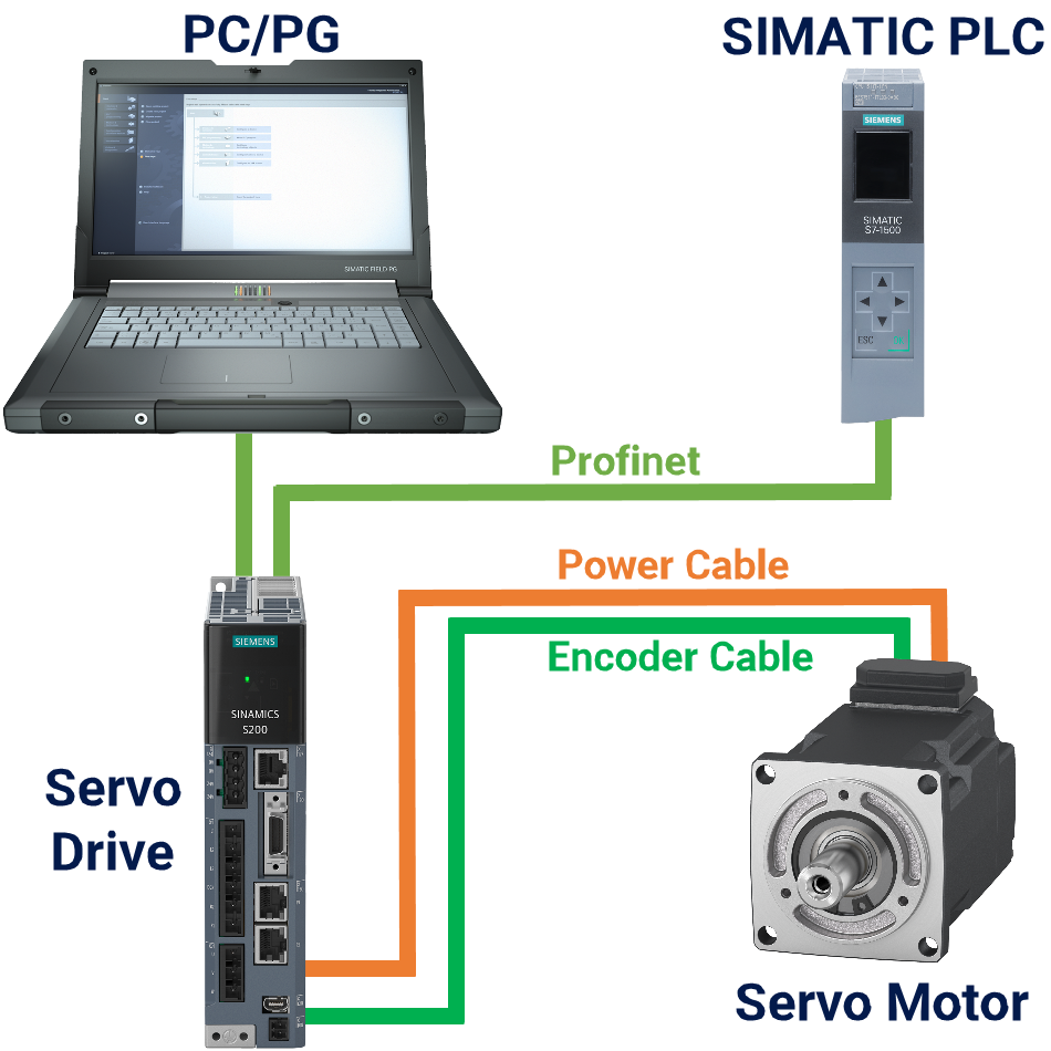
Programming the PLC S7-300 to interface with a servo motor using Modbus involves several steps:
Step 1: PLC S7-300 Set Up Communication Parameters
- Open your PLC programming software (e.g., Siemens STEP 7).
- Configure the communication interface (e.g., CP341) for Modbus communication.
- Specify the communication parameters such as baud rate, data bits, parity, and stop bits.
Step 2: PLC S7-300 Define Modbus Communication Settings
- Define the Modbus communication settings in the PLC program, including the slave address of the servo motor, communication timeout, and error handling mechanisms.
- Use appropriate function codes (e.g., Read Coil, Read Holding Registers) to exchange data with the servo motor.
Step 3: PLC S7-300 Implement Communication Instructions
- Write communication instructions (e.g., MODBUS_RD, MODBUS_WR) in your PLC program to establish communication with the servo motor.
- Use read instructions to retrieve servo motor status and feedback data (e.g., position, velocity) and write instructions to send control commands (e.g., target position, velocity profile) to the servo motor.
Step 4: PLC S7-300 Test and Debug
- Verify communication by sending and receiving data packets between the PLC and servo motor.
- Validate control commands by observing the motor’s response to ensure it moves according to the specified trajectory and follows the commanded motion profile accurately.
- Debug any communication issues or errors encountered during testing.
Step 5: PLC S7-300 Fine-Tuning and Optimization
- Fine-tune the PLC program and servo motor parameters as needed to optimize motion control performance.
- Adjust parameters such as PID gains, acceleration/deceleration ramps, and position feedback resolution to achieve desired motion characteristics.
- Monitor system performance and make iterative adjustments to improve motion control accuracy and efficiency.
Step 6: PLC S7-300 Documentation and Maintenance
- Document the Modbus communication settings, PLC program logic, and servo motor configuration for future reference and troubleshooting.
- Maintain clear and comprehensive documentation to facilitate system maintenance and knowledge transfer.
Example Ladder Logic Program (Simplified):
NETWORK 1
TITLE PLC Modbus Interface with Servo Motor
RLO_1 := MODBUS_RD (ServoMotor_Address, HoldingRegister_1); // Read servo motor status
RLO_2 := MODBUS_RD (ServoMotor_Address, HoldingRegister_2); // Read servo motor feedback data
NETWORK 2
TITLE PLC Modbus Interface with Servo Motor
IF ControlCondition THEN
MODBUS_WR (ServoMotor_Address, HoldingRegister_3, ControlCommand); // Write control command to servo motor
END_IF;
This is a simplified example. The actual programming may vary based on your specific PLC model, servo motor, and application requirements. Refer to your PLC and servo motor documentation for detailed programming guidelines and examples.
Example Function Block (Simplified):
FUNCTION_BLOCK FB_Modbus_Interface
TITLE = ‘PLC Modbus Interface with Servo Motor’
VAR_INPUT
ControlCondition : BOOL; // Control condition for writing command
ControlCommand : INT; // Control command to be written
END_VAR
VAR_OUTPUT
ServoStatus : INT; // Status data read from servo motor
ServoFeedback : INT; // Feedback data read from servo motor
END_VAR
VAR
ModbusAddress : INT := ServoMotor_Address; // Modbus address of servo motor
END_VAR
IF ControlCondition THEN
// Write control command to servo motor
ModbusWrite(ModbusAddress, HoldingRegister_1, ControlCommand);
ENDIF;
// Read servo motor status and feedback data
ServoStatus := ModbusRead(ModbusAddress, HoldingRegister_2);
ServoFeedback := ModbusRead(ModbusAddress, HoldingRegister_3);
Ladder logic example:
NETWORK 1
TITLE PLC Modbus Interface with Servo Motor – Read Data
// Read servo motor status and feedback data
LD MODBUS_RD (ServoMotor_Address, HoldingRegister_1, StatusData); // Read servo motor status
LD MODBUS_RD (ServoMotor_Address, HoldingRegister_2, FeedbackData); // Read servo motor feedback data
// Additional logic based on StatusData and FeedbackData
NETWORK 2
TITLE PLC Modbus Interface with Servo Motor – Write Command
// Write control command to servo motor if condition is met
LD ControlCondition; // Control condition for writing command
L P (ControlCondition); // Positive edge detection for condition
S B ControlConditionFlag; // Set flag to indicate condition is met
L DB ControlConditionFlag; // Check if condition flag is set
T DB ControlConditionFlag; // Reset condition flag
// Write control command to servo motor
LD ControlConditionFlag; // Check if condition flag is set
AND ControlConditionFlag ControlCommand; // Control command to be written
LD MODBUS_WR (ServoMotor_Address, HoldingRegister_3, ControlCommand); // Write control command to servo motor
In this ladder logic example:
MODBUS_RDinstructions are used to read data (status and feedback) from the servo motor.- The control condition is checked, and if it’s met, a control command is written to the servo motor using the
MODBUS_WRinstruction. - Additional logic based on the status and feedback data can be implemented as needed for your application.
Please note that the specific syntax and function block names may vary depending on the version of STEP 7 software you are using and the configuration of your PLC. Make sure to refer to the documentation and function block library provided by Siemens for accurate implementation.


My relatives always say that I am killing my time here at web, however I know
I am getting knowledge all the time by reading such fastidious articles.
I have read so many content on the topic of the blogger lovers but this piece of writing
is really a pleasant paragraph, keep it up.