Robotic Arm Gripper Designs, the capacity of robots to hold and move items has been critical to their growth. Manufacturers may gain the benefits of precision, performance, and productivity by adopting end-effector equipment for selecting, putting, and packaging products. Grippers are classed based on their design, power source, and application. When it comes to industrial grippers, one of the most basic types is the parallel motion two-jaw gripper, which is widely used to lift things. The needle gripper and the O-ring gripper are two further design kinds. Depending on the application, industrial grippers can be hydraulic, pneumatic, or electronic. Despite the fact that the number of grippers now available on the market has increased over the years, there are still many complicated jobs that robots cannot perform.
When grasping fragile things with the appropriate force, robotic grippers have a problem. A gripper handling fruit or food, for example, must grasp the fruit firmly enough so it does not slip out of their grasp but gently enough so the fruit does not get damaged. While human fingers are soft and can conform to objects, this is not inherent in a robotic gripper, which is typically made of metal or other materials with a hard surface. To address this difficulty, designers created grippers made of softer materials, allowing robotic grippers to handle fragile items, giving rise to the field of soft robotics. Soft robotics is a branch of robotics that focuses on robots composed of soft materials comparable to those found in real animals, such as octopus tentacles or a human squishy finger. Recent advances in soft robotics enable robots to overcome previous barriers and enter new markets.
Dexterity is another issue for gripper designers to consider. Many conventional gripper designs have two or three stiff fingers. Even while they can do select and place tasks well, they are not well adapted to more complicated manipulation tasks. To be useful and effective, the design must produce complicated geometries, mechanically adapt to the shape of an item, specialize in gripping and manipulating using ultra-sensitive touch sensors, and have a low impact energy to resemble a human hand.
This article investigates the most recent industrial and research gripper designs to address the question: What gripper design can handle most items regardless of fragility, shape, or weight? Thus, we categorized the grippers based on their mechanical design, number of degrees of freedom (DOF), type of actuation, and the shape of the gripping objects, focusing our research on determining which gripper has the greatest handling capabilities.
Design Configurations for Robotic Arm Grippers
To understand how grippers are developed, first consider how humans interact with, hold, and move items in their daily lives. A study conducted by the Max Planck Institute for Intelligent Systems educated computers to interpret, mimic, and synthesize human gripping. The study’s analysis encompasses sophisticated three-dimensional item forms, comprehensive contact information, hand attitude and shape, and three-dimensional body movements. Similar studies were carried out in, where the sorts of grips utilized were categorized depending on the type of object, its form, and weight. Figure 9.1 depicts many sorts of gripping.
According to what has previously been said, gripping modes are also characterized depending on the geometry of the item, which is depicted in Figure 9.2: parallel or flat grasping mode, cylindrical gripping mode, and spherical gripping mode. Other categories derived from these three are offered as subsets of the primary categories, such as Tip mode, Hooke mode, and Lateral mode. For example, lateral mode is a subset of parallel mode in which the object’s thickness is hundreds of times less than its perpendicular area. There are three basic categories that classify the design of robotic grippers based on their mobility: completely confined, under constrained, and deformable.
Table 1 shows the numerous subgroups within those categories based on the actuation mechanisms. This paper examines each categorization of robot arm grippers, concentrating on the benefits and drawbacks of each.
Figure 9.1 depicts a classification of grabbing based on the needed power and precision for various object shapes and wrap kinds.
Figure 9.2 depicts a generalized categorization of grasping modalities based on the geometry of the item.
Table 1 shows the many types of robotic grippers based on their design configurations and actuation mechanisms.
Completely constrained Gripper Mechanism
Completely confined finger mechanisms are devices that have a DOF equal to the number of actuators and allow the tip of the finger to follow a specified route. The number of degrees of freedom is calculated using the Gruebler-Kutzbach equation, which is shown below:
𝑀=3𝐿−2𝐽 (1)
where M is the total DOF, L is the number of links, and J is the number of joints. Consider the fully constrained mechanism shown in Figure 9.3, which has three links (𝐿𝑖) and four joints (𝑗𝑖); using Equation (1), the total number of DOF is one. As a result, this robot just need one actuator to create motion. This characteristic allows the gadget to produce a considerable amount of torque, allowing the gripper to hold heavy items. The majority of these devices employ 1 DOF to control the gripper’s motion, limiting the complexity of the things that the gripper can grasp. To address this issue, researchers increased the number of degrees of freedom (DOF) in the grippers to improve their capacity to handle complicated items at the price of their output torque. Completely confined finger mechanisms are classified into two types based on their design: compliant mechanisms and stiff connections.
Figure 9.3: A completely constrained system is compared to an under constrained mechanism.
Mechanism of Compliance
A flexible mechanism that transmits force and motion via elastic deformations is known as a compliant mechanism. Compliant mechanisms feature fewer moving components, making them lighter. Furthermore, because compliant mechanisms require fewer assembly pieces, friction has a greater influence on them than rigid connections. Furthermore, fewer assembly pieces lessen undesired nonlinear effects on compliant mechanisms like as backlash and noise. Compliant mechanisms are typically made of 3D printed materials, which lowers their production costs. However, because the links are flexible, they are significantly weaker than rigid links, limiting the output torque capability. Topological optimization, as presented for a gripper with three flexible fingers, is a common design method for compliant devices. The optimization’s main goal was to make modelling of interactions between the gripper and the objects easier. Figure 9.4 depicts the optimization steps for the gripper design. To derive the objective function, the optimization model takes into account the loading pressure and traction frictions for this scenario. The acquired apparatus is controlled by pulleys and cables.
Figure 9.4 depicts the steps of topological optimization of the finger compliant mechanism.
In [1,] an example of a compliant mechanism is used for each finger of a three-finger flexible gripper. Figure 9.5 depicts the finger mechanism doing linear movements. The finger mechanism was made of thermoplastic elastomer (TPE) and was designed to interact with unexpected situations as well as handle delicate things of various sizes. Furthermore, the gripper mechanism uses only one linear actuator to activate all three fingers at the same time, resulting in the identical displacement on each finger.
Figure 9.5: Linear motion performed by a flexible finger.
A comparable design that focuses on the ideal design of a 3D-printed constant force-compliant finger. For high-speed handling of fragile objects, this finger mechanism employs a force control method. The gripper actuation system, comprising the jaw and the FRM, is depicted in Figure 9.6. The gripper mechanism is pneumatically operated and contains two complaint mechanisms that serve as springs.
Figure 9.6: A gripper’s actuator system, comprising the jaw and FRM.
Sensors are included into the design of other compliant grippers. For automated micro-assembly operations, this compliant gripper incorporates a location and grasping/interaction force sensor. The integrated sensor, on the other hand, restricts the workspace to 2.2 mm and has a gripping force of 16 mN. However, this may not be a forthcoming feature for the specific use of this gripper. The complaint mechanism is depicted in Figure 9.7, which includes integrated position and force sensors as well as a piezo resistive strain gauge for regulating the end-effector. This gripper mechanism employs finite element topological optimization as well. The author validated the viability of this technique by comparing the optimization findings with an experimental setup.
Figure 9.7: Complaint mechanism structure with integrated sensors.
Rigid Connections
In contrast to compliant systems, rigid linkages may create a high output torque while remaining stiff. However, in order to avoid injuring the handled items, this gripper system requires force sensors. This paper presents a cable-driven adaptive multi-DOF finger with an integrated mechanical sensor to regulate position and output torque. This finger mechanism is built of Acrylonitrile Butadiene Styrene (ABS) and is capable of producing motion in a single plane. This finger mechanism’s design maximizes output forces along a preset route, resulting in a gripper mechanism capable of holding items up to 55mm in diameter and 800 grams in weight.
Figure 9.8 depicts the gripper mechanism’s kinematics during the design trajectory. Another stiff gripper with comparable qualities. This stiff gripper is a four-finger hand gripper with three degrees of freedom (DOFs) on each finger that is activated by cables. The fingers of the hand gripper have similar proportions and are made out of two phalanges. Other rigid grippers include changing friction surfaces, which improve the gripper’s manipulability and dexterity. This gripper’s texture is made of Polylactic Acid (PLA) and TPU, and its friction is controlled by the actuation of two pulleys connected to DC motors, as shown in Figure 9.9.
Figure 9.8: Kinematic schematic of the design trajectory’s finger mechanism.
Figure 9.9: Surface-changing friction system.
One restriction of stiff linkages is the requirement for a precise control method. Because of the nature of the force sensor, obtaining this functionality is difficult. As a result, some writers employ a fuzzy logic controller to convert experimental data into an accurate control plan. Figure 9.10 depicts the author’s experimental setup for validating the behaviour of this strategy. Closed-loop links are used in other stiff link systems. As shown in Figure 9.11, this finger gripper features two parallel grippers made of symmetric parallelograms.
Figure 9.10: Gripper setup with one moving finger (force sensor) and one fixed finger (slip sensor) to improve control.
Figure 9.11: Finger gripper made out of two parallel symmetric parallelogram grippers.
The benefit of this kinematical design is that the model is easier to apply, guaranteeing that the tool reacts appropriately to the gripping forces and spring stiffness. Furthermore, some rigid link grippers incorporate lead screws to improve precision. The former employs a gripper modelled like a chuck clamping mechanism, as seen in Figure 9.12. The location of items is provided by a closing motion mechanism in this gripper. The latter employs a slider-crank system, as seen in Figure 9.13. This stiff link system can handle goods weighing up to 5kg as well as fragile products such as eggs. Both gripper systems have the benefit of self-locking, which saves energy by not requiring the motors to be engaged all of the time. However, owing of its large mechanical advantage, this sort of gripper has a slow-motion difficulty.
Figure 9.12: Chuck type system assembly and functioning.

Figure 9.13 shows the gripper holding an egg without shattering it.
Electromagnets are used in other systems to activate stiff linkages. For example, an electromagnet-actuated gripper for fabric handling. The gripper employs a slider-crank mechanism, as shown in Figure 9.14. Multi objective genetic algorithms are used to optimize the design of more complicated electromagnet-actuated grippers. The scientists modelled the actuator as a stack composed of individual actuator parts organized in series and parallel arrays in four different configurations. The gripper’s accuracy has enhanced as a result of this optimization procedure when compared to other grippers of the same type. However, employing electromagnets requires a significant amount of energy, making them unsuitable for autonomous applications.
.
Figure 9.14: Electromagnetic gripper.
Figure 9.15 depicts the Salisbury hand, the first successful humanoid robot hand developed as a sophisticated end-effector for grasping experiments. This hand features three joints on each finger, allowing it to simulate the dexterous grasping of the human hand to some extent. The fingers are activated by steel wires that travel via Teflon-coated flexible tubes. Each cable is tensioned by a DC brush-type motor via a gear reducer. The actuator package may be installed on the robot’s forearm thanks to the flexible conduit that allows cables to be routed around the wrist.
Figure 9.15: Salisbury hand finger joints.
The DHL Hand is an open skeleton hand constructed of aluminum and steel that has exceptional dexterity and precision when manipulating a range of things. Each finger has three unique joints that are controlled by their own actuators. In all actuation systems, brushless dc motors, teeth belts, harmonic drive gears, and bevel gears at the base joint are employed. The base joint, as depicted in Figure 9.16, is a differential bevel gear type, allowing for two independent movements. The two actuators may be fully used, allowing the joint to flex or expand as needed.
Figure 9.16: Actuation systems control three finger joints of the DHL hand using brushless dc motors, teeth belts, harmonic drive gears, and bevel gears at the base joint.
The Barrett hand is a well-known example of a hand utilized in industry and research on grasping and manipulation. Each finger on the Barrett Hand in Figure 9.17 is driven by a motor, and each motor controls two joint axes. A Torque switch mechanism applies torque to these joints. When a fingertip makes the first touch with an item, it locks both joints, turns off motor currents, and waits for further instructions from the microprocessors.
Figure 9.17. Finger mechanism of a Barrett hand.
Underconstrained Mechanism
When compared to entirely confined mechanisms, under constrained mechanisms have a greater range of motion capacity. The increased motion is due to the DOF being more than the number of actuators, which adds additional flexibility to handle irregularly shaped objects. The extra DOF is often passively operated by springs to maintain the structure, as seen in Figure 9.3, which depicts a 2-DOF under-constrained mechanism. However, as with under constrained compliant systems, the gripper’s design can include the effects of the spring without introducing it. The authors offer an example of this type of mechanism in Figure 9.18, in which they created a robotic gripper with compliant cell stacks for industrial component handling.
Figure 9.18. Robotic gripper with compliant cell stacks mechanism
Another example is given, who created an underactuated robotic gripper with three fingers inspired by the twisted origami structure illustrated in Figure 9.19. Each gripper finger is actuated by a cable that is controlled by a central servomotor. Although the gripper mechanisms can handle items with complicated forms, their maximum payload capacity is 1.5 N. Produced a passive-compliant piezo actuated micro-gripper (Figure 9.20); while the designs provide a 3D printed Gripper for Cloth Manipulation and position control (Figure 9.21).
Figure 9.19: An origami twisted tower inspired an underactuated robotic gripper with three fingers.
Figure 9.20: Piezo-actuated passive-compliant micro-gripper.
Figure 9.21: 3D Printed Gripper for Cloth Manipulation.
Another restriction of this sort of gripper is the requirement for a force sensor capable of monitoring force distribution on a surface. To that purpose, the authors created a gecko-inspired gripper with sensors made of ABS polyimide or Mylar polyester and a metalized surface (Figure 9.22). The sensor is built in place using thin adhesive films on each finger and monitors the change in capacitance when an adhesive area comes into touch with a surface. The authors created another sensor for a compliant adaptive gripper that included an implicit force. The gripper can calculate the output force by observing the gripper’s deformations.
The authors employed a generic numerical network model (NTM) to compute the system’s deformation. The NTM uses a hand-eye camera to determine the mechanism’s node coordinates (Figure 9.23). The NTM then computes the gripping force of the gripper using the node information. The suggested mechanism is the first fin-ray-based gripper that can perform adaptive grasping and intrinsic force sensing without the need of a force sensor. A gripper with comparable skills, who created a unique compliant constant-force gripper based on buckling fixed-guided beams (Figure 9.24). The gripper has a passive compliant constant-force mechanism. Using a mix of positive and negative stiffness mechanisms, the gripper may create a constant-force output. A bi-stable buckling fixed-guided beam serves as the negative stiffness mechanism.
Figure 9.22: A whole gripping movement sequence.
Figure 9.23: Theoretical gripper deformation as represented by the overall numerical network model.
Figure 9.24: Structure model of a compliant mechanism.
Rigid Connections
Load capacity is greater in under constrained rigid gripper mechanisms than in under constrained compliant mechanisms. However, as compared to completely limited gripper systems with stiff linkages, their load capacity remains modest. As a result, they have a mean output load capacity. Furthermore, most designs of under constrained grippers incorporate optimization strategies to improve kinematic capabilities. The authors offered a geometric design with three-phalanx underactuated fingers as an example of an optimized gripper. The stability of two classes of three-phalanx cable-driven underactuated fingers is being investigated in this work. Furthermore, the theory for optimum gripper design is described, including an objective function that maximizes forces normal to the contact trajectory while preventing contact loss and ejection (Figure 9.25).
Figure 9.25: Object clamping sequence to avoid ejection from the gripper design.
Another example of optimization is a multi-modal adaptive gripper with the ideal design of a re-configurable finger created to improve robotic manipulation without losing gripping efficiency (Figure 9.26). Using a concurrent multi-start search technique, the optimization problem maximizes the workspace volume for a wide variety of items. To compute the dexterous manipulation workspace, this technique considers all potential locations of the objects during the in-hand manipulation. The technique generates a planar point cloud by clustering all configurations into a collection of points. The alpha-Shape technique is used to determine the bounding volume of the point cloud, which formalizes the abstract shape of the provided collection of points using Delaunay triangulation.
Figure 9.26: Multimodal adaptive gripper with optimum reconfigurable finger design.
Other methods include the addition of spines to a gripper’s gripping capability. For example, a passive spine gripper created for a climber robot that can grip hard rocky surfaces. With six fingers, this gripper is ideal for spatial exploration in unexpected areas. The mechanism (Figure 9.27) is equipped with twin spines that allow it to clamp to various surfaces. The finger component is attached to a preload spring within the gripper. The finger mechanism is controlled by a servomotor-pulley actuator. Furthermore, a servo motor effortlessly pulls a nylon gut linked to each fingertip to release or detach the gripper from the surface. The gripper has a range of 120 (ϕ=60) degrees and a holding force of 4.7 N. The author used energy techniques to determine the spring stiffness.
Figure 9.27: Dual spines allow the mechanism to clamp to diverse surfaces.
Rigid linkages have the disadvantage of necessitating more rigid links than entirely confined devices. As a result, some gripper systems may be bulky. To circumvent this problem, several writers used cable-driven actuation. Consider the open-loop gripper design, which is a two-finger underactuated hand with cable-driven actuation (Figure 9.28). Each finger is tendon-driven, with a 21-mm pulley diameter connected to an MX-28 Dynamix servo producing 2.5 Nm at 12 V. The gripper is capable of holding both square and round items. The gripper was evaluated utilizing an Ascension trakSTAR sensor to measure the displacement position and orientation at the gripper’s center.
The sensor supports 6-DOF tracking with a spatial resolution of 0.5mm and 0.002 rad. Furthermore, the gripper has a total stroke length of 0 to 103 mm and a holding grip force of 8.9 0.35 N at the fingers. The essay focuses on the design rather than the mathematical considerations. The authors, on the other hand, present a library for constructing underactuated grippers. Figure 9.29 shows the Schunk SVH hand, which is one of the most compact designs ever developed. The motors of the humanoid Schunk hand are entirely placed in the wrist, saving a lot of room for the mechanics.
Figure 9.28 shows the internal gripper assembly.
Figure 9.29. Schunk SVH hand
Another analogous two-finger underactuated device is described, this time having cable-driven actuation and active tactile manipulation. The fingertip touch objects are constructed of a rubber-like skin with inner white pins (1 mm in diameter). The tip is entirely 3D-printed using a multi-material 3D printer (Stratasys Objet 260 Connex), with the stiff regions printed in Vero White and the responsive skin in the rubber-like TangoBlack+. An acrylic glass separates the electrical components from the tip, which is filled with RTV27905 silicon gel, for compliance. The rubber pins that protrude from the tip surface are illuminated by a 6-LED circuit (Figure 9.30).
The whole range of object orientations is determined by object size and form, and ranges from −34.4∘ to 32.3∘ for a 20 mm diameter cylinder to −21.8∘ to 20.6∘ for a 35 mm diameter cylinder.
Figure 9.30: Layers utilized to employ LEDs as sensors at the gripper’s tip.
For engagement with an unexpected environment, the authors of [fig 9.31] created an adaptive gripper with transition capabilities between a precise pinch and a compliant grasp. Each finger contains just one stiff link, one belt, one fingertip frame, and one motor (40 Watt ECX16 motor) for flexion motion (Figure 9.31). The finger shape allows for exact parallel pinching as well as very flexible and secure gripping with uniformly distributed pressure. The gripper is made of flexible belt materials with high rigidity, and the fingers are made of ABS. The gripper has a grabbing power of around 13 N and can handle a variety of things such as a driller, a baseball ball, a hammer, a cup, tape, and so on.
Figure 9.31: The gripper’s double-actuated gear and belt arrangement.
Furthermore, in [fig 9.32], the authors introduced an underactuated origami gripper for varying the stiffness of the gripper joints (Figure 9.32). This two-finger gripper is made of shape memory polymers and is powered by a tendon-driven system with stiffness joints that can be adjusted. Without a control method, the controlled compliance of the fingers restricts the contact forces at the required magnitude. As a result, the gripper does not require a sensor, making control easier and allowing it to grab delicate and tiny things like an egg, foam, and a penny.
Figure 9.32: An underactuated origami gripper that may be used to adjust the stiffness of the gripper joints.
[fig 9.33] depicts another cable-driven robot gripper with a passively switchable underactuated surface, as well as a physic simulation based on parameter optimisation for its design. The author presented a fingertip gripper with an underactuated surface (Figure 9.33). The activation of a single motor creates three grasp modes in sequence with the spring-loaded passive switching mechanism: approaching the object as a typical parallel gripper, drawing things within the hand with an actuated fingertip crawler, and power grabbing the object as an underactuated gripper. The authors demonstrated experimentally that a prototyped gripper with the suggested construction picked up a 3-mm thin sheet and a softcover book from a flat surface. Furthermore, using an encompassing grasp, the gripper can lift cylindrical-shaped items from surface to end. This gripper has a workspace of roughly 200 mm and a grabbing force that is flat against the item size and surpasses 20 N.
Figure 9.33: A cable-driven robot gripper with an underactuated surface that may be switched passively.
Figure 9.34 from the publication depicts an adaptive three-fingered prismatic gripper with passive rotating joints. The hand’s body is constructed of 3 mm laser-cut Delrin and 3D-printed ABS components (produced on a Fortus 250mc). The fingers are 3D-printed as well, with the finger pads made from a cast of Smooth-On VytaFlex 30 urethane rubber. Each finger is made up of a single joint finger that is linked to the prismatic joint through a perpendicular passive rotational joint to the palm. The rotating joints enable the fingers to move between spherical and cylindrical grasps passively, while the finger joint allows the fingers to wrap around the gripped item. The gripper can handle goods ranging in size from 17.4 mm to 145 mm, a set of washers ranging in size from 9.8 mm to 50.8 mm, a credit card, different tools, and other items, according to the report.
Figure 9.34: Adaptive three-finger prismatic gripper with passive rotating joints.
The authors of [fig 9.35] offer an underactuated gripper based on screw theory that exploits joint compliance with an efficient mathematical model of soft robotic fingers (Figure 35). The mathematical model allows the gripper designer to investigate the impact of various variables such as the trajectory of the fingers, overall stiffness, contact force distribution, and so on. The gripper has an 85 mm range for cylindrical and spherical items such as a cup, tennis ball, small box, and so forth. Furthermore, the gripper is made of ABS and can withstand 43 N. Finally, [fig 9.36] depicts the design and analysis of a unique robotic gripper coupled with a three-phalanx finger for medical applications.
The mechanism functions as two grippers in one, one tiny for gripping little things (the embedded one) and one larger for handling large goods (Figure 9.36). This innovation enables the gripper to participate in more daily tasks.
Figure 9.35: An underactuated gripper that takes use of joint compliance.
Figure 9.36: A novel robotic gripper for medical applications that incorporates a three-phalanx finger.
Other techniques, such as [fig 9.37], which presents a re-configurable gripper for robotic autonomous depalletizing for supermarket logistics, employ stiff connections with linear actuators. The depalletizing gripper features two extensible forks that can move along a rail as well as two suction systems outfitted with suction cups that are controlled by a closed-loop controller (Figure 9.37). The gripper can grasp items ranging in size from 15 to 50 cm and weighing up to 43 N.
Figure 9.37 shows a gripper for depalletizing that has linear actuators and stiff linkages.
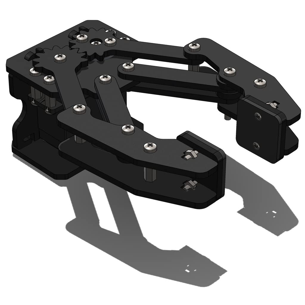
Rotary actuators are another kind of actuation used in stiff links. An underactuated four-bar connection (Figure 9.38) is suggested in [fig 9.38]. The gripper is operated by a single Maxon EC45 70-W actuator, which delivers a reliable pinch under a variety of environmental conditions. The fingertips can glide over items with sloping surfaces that range in diameter from 11 mm to 85 mm. Lightweight items can also be handled by the gripper. In order to ascertain the actuator’s operating principle, the research additionally examines the static and kinematic data using Plücker coordinates. The outcomes were applied to the linkage’s dimensional synthesis in accordance with various sliding and lifting criteria.
The design suggested in [fig 9.39] also employs rotary actuators, and it calls for a 3D-printed robot hand with three underactuated fingers that are powered by linkages and have the ability to reposition two or three of their fingers (Figure 9.39). Three phalanges make up each finger’s mechanism, which is constructed from a chain of hard links. The gripper design can interact with items of various shapes and sizes, such as cylinders up to 81 19 mm in size and spheres up to 70 mm in diameter, while still retaining a 15 N contact force. The gripper has springs that allow it to return to its original position. The mechanism’s dimensions were established by employing a grabbing optimization for various items.
Figure 9.38: A gripper with a four-bar connection that is underactuated.
Figure 9.39 shows one of the three linkage-driven under-actuated fingers in kinematic motion.
Finally, [fig 9.40] shows another rotary actuator gripper. An adaptable robotic gripper that was 3D printed but is underactuated is shown in this post for use in uncertain surroundings. Each of the gripper’s three fingers features an underactuated mechanism made up of five joints and a spring (Figure 9.40). Thermoplastic elastomer (TPE), PLA, and ABS are the components of the grippers. Additionally, the gripper can support weights of 2.5 kg and spherical items up to 75mm in diameter, including pencils, bottles, and whiteboard erasers. In order to choose the spring, the authors also provided a kinematic and quasi-static study of the finger.
Figure 9.40 shows a robotic gripper that is 3D printed but is underactuated to interact with uncertain situations.
Other designs, like [fig 9.41], employ pneumatic actuators. A high-payload hybrid robotic gripper with soft organic actuators was designed and demonstrated by the authors. The suggested actuator can move linearly in one DOF along its axis. The geometric characteristics for customization and steady linear movement are simply designed as a result of the repeated trapezium facets (Figure 9.41). Polypropylene rubber is used to mold the bottom cover and the actuator body. The actuator has a top air vent that may be attached to pneumatic fittings. A soft-actuator joint and solid supporting structures with motion restrictions make up the two major parts of the gripper.
Based on the geometric characteristics, an analytical model of the actuator is created to depict the relationships between the output force, internal pressure, and axial displacement.
Figure 9.41. Soft organic actuators on a high-payload hybrid robotic gripper
Deformable Grippers
Single Mass Gripper
Individual mass grippers manipulate objects by changing their shape. As opposed to grippers that are entirely constrained or have an underconstrained actuator, this type of gripper does not have a clear link between the deformation and the actuator mechanism. Single mass grippers subsequently deform until they have wrapped the desired item. This kind of gripper, which can handle a wider range of items regardless of their shape, employs pneumatic or cable-driven actuation. The use of pneumatic actuation, which displays a prestressed soft gripper with three fingers for handling food, however, restricts the mobility of the gripper notwithstanding their capacity for object manipulation. The actuator is made of two 3D-printed components: a sealed cover and a soft chamber with a stiff connection.
By extending and gluing a non-stretched cover, the soft chamber is prestressed (Figure 9.42). Without inflating the soft actuators, the gripper may achieve a high contact area while gripping with a wide initial opening. The fingers/actuators are made of a substance that resembles rubber. To pressurize the actuator, the scientists employed an air compressor (JUN-AIR 3-4) and an electro-pneumatic regulator (SMC ITV 2030). The 87 mm-long soft actuator can pick up things weighing 75.2 g with an accuracy of 80%. To determine the ideal dimensions, the author used a finite element simulation.
Figure 9.42: A prestressed soft gripper with three fingers for food handling features a soft chamber with a stiff connection and a sealed lid.
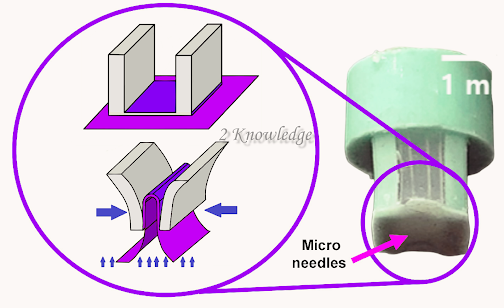
Similar concerns have been raised by other authors [fig 9.43], who describe a single mass soft robotic gripper integrated with Microneedles for handling fragile textiles. The gripper material is an elastomer. Using four microneedles, the gripper hooks the delicate fibers. The gripper’s actuator is a vacuum pump, which deforms the elastomer once it is in place to handle the textiles (Figure 9.43). Although the author does not utilize any pressure sensors, other options include inserting soft pressure sensors at the gripper’s tip. Aside from its size, the vacuum pump consumes more energy than a standard air compressor.
Similarly, [fig 9.44] an origami-inspired gripper operated by a SMA actuator is created for picking things of varying shapes and sizes. The gripper’s design is inspired by a reconfigurable suction gripper (Figure 9.44). The gripper, made of stiff and soft components and powered by small shape memory alloy actuators, can efficiently self-fold into three form modes. The major goal is to select large and tiny, flat, thin, cylindrical, triangular, and spherical items ranging in diameter from 2 mm to 43 mm and weighing less than 5.2 N.
Figure 9.43: A single mass soft robotic gripper equipped with Microneedles for sensitive fabric handling.
Figure 9.44: An origami-inspired gripper controlled by a SMA actuator, as well as the various forms that the gripper may take due to the SMA actuators housed within it.
Other systems employ cable-driven actuation to save energy while increasing manipulability. However, because of the intricacy of the deformation model, regulating the gripper motion becomes difficult. The authors of [fig 9.45] demonstrate this type of gripper. The scientists created a gecko-inspired multi-legged gripper with a configurable stickiness parameter. A self-adaptive dry adhesive technology allows the gripper to manage flat and curved items. The system is made up of four symmetric adhesive units that are individually regulated by two adaptive-locking mechanisms for compression and rotation, as well as one peeling mechanism.
To guarantee close contact with the items, the two adaptive-locking mechanisms may adjust to surfaces with different heights and curvatures (Figure 9.45). Furthermore, the lock adaption setup allows for equitable load sharing for a secure attachment. The peeling mechanism quickly rips the sticky surfaces away from the substrate, allowing for simple removal.
Figure 9.45. Multi-legged gripper inspired by a gecko with a configurable adhesion parameter that generates a tight hold due to the gripper’s flexibility.
Another flat dry sticky soft gripper with a soft actuator, micro spine, and a bioinspired design based on a gecko’s toe and a cat’s foot was presented in [fig 9.46]. The soft gripper features an enhanced design that improves its overall grabbing capabilities on smooth or bumpy surfaces. Using SMA coils, the design simulates two phalanges, proximal and distal (Figure 9.46). The SMA coils are located on the base layer’s backside, opposite an adhesive layer. A flexible sensor monitors the force between the two layers of the finger. Micro-needles on the fingertips improve gripping abilities.
Figure 9.46: System consists of SMA actuators, structure, and soft gripper cooling system.
Finger with a Single Mass
To actuate each of their fingers, single mass fingers modify their shape. Because of the actuation of the fingers, this gripper mechanism may grasp items of various shapes, and it has similar advantages and disadvantages to single mass grippers. Using several grippers, for example, makes it easier to control the gripper; an increase in the number of grippers provides for a better distribution of the forces created, reducing the reliance on an exact control technique. However, the issue of bulkiness is more pronounced with this type of gripper since the actuator must bend numerous fingers rather than just one.
To provide some instances, The soft robotic gripper illustrated in [fig 9.47] has three fingers and employs particle transmission. The fingers can grab a variety of things, including nipper pliers, tape, haptic devices, and electric screwdrivers. Furthermore, the gripper has a vertical force gauge that measures a grabbing force of about 20 N at the tip. The authors used mass conservation and the idea of incompressible homogeneous neo-Hookean materials to model the system. Furthermore, the actuators were made from molded silicone rubber reinforced by double-stranded woven fiberglass thread and PLA (Figure 9.47). The suggested actuator is a slightly modified version of the well-studied fiber-reinforced soft pneumatic actuator.
Figure 9.47: Particle transmission actuates a soft robotic gripper.
Furthermore, [fig 9.48] shows a soft robotic gripper with an active palm and programmable fingers executing sophisticated tasks such as rolling a pen or pouring a glass of water. The gripper may be used in a variety of applications, including robotic manipulation, medical applications, mobility, rehabilitation, and assistive robotics. The gripper’s fingers are made of EcoFlex silicone elastomers. The position of the fingers is controlled by stepper motors, micropumps, and solenoids (Figure 9.48). Each finger features three distinct pneumatic chambers, allowing each finger to move freely. The concept of optimization over earlier iterations is discussed but not defined. The author, on the other hand, does a workspace study to identify the entire active area. Furthermore, the soft gripper is based on pre-charged pneumatic soft actuators.
Figure 9.49 shows a pre-charged pneumatic (PCP) gripper with a silicone chamber and one air line for pressurization. The pressure inside the silicone chamber is controlled by a check valve. When the fingers are pressed, tensile wires or tendons are used to adjust their form. The actuator body is made of silicone rubber, with an inextensible layer connected to the bottom of the actuator and capable of gripping delicate things such as tomatoes or eggs.
Figure 9.48: Soft robotic gripper with active palm and programmable fingers.
Figure 9.49 shows a soft gripper that uses a tendon to charge the soft pneumatic actuators.
Another gripper is shown in [fig 9.50], which includes both stiff and soft materials. The gripper features a single interior chamber that is pressurized and regulates the position. The authors proposed this design to simultaneously improve fingertip force and actuation speed by optimizing parameters such as degree of bending, rigid structure ratio, longitudinal strain by modifying chamber shape, and the relationship between soft and rigid materials in the same finger (Figure 9.50). Furthermore, the gripper is controlled by two pneumatic pumps (DAO-370A), providing for a large area appropriate for teleoperation. With a maximum permissible weight of 28.7 N, the gripper can handle things such as a drill driver, a coffee cup, and a banana. The finite element technique (FEM) and a simulation based on the hyperrealist Mooney-Rivlin model were used to optimize the design parameters.
Figure 9.50 depicts the circular route taken by the soft gripper’s fingertip when pressure is applied to its chamber.
Another concept for medical uses is a pneumatically powered gripper with retractable, telescopic fingers, as shown in [fig 9.51]. To activate this silicone rubber gripper, the scientists employed two low-pressure mini-air pumps. In addition, the scientists used an optical motion capture system comprised of eight cameras to track the gripper’s angular displacement (Figure 9.51). To improve measurement precision, the gripper features retroreflective indicators on the upper surface of the actuator. The soft actuator has a range of motion of 0 to 105 degrees. The gripper has a grab force of 14.53 N and can handle things such as a medium mustard bottle, a water bottle, an egg, and a drill driver. To comprehend the structure’s inflating behavior, a Finite Element Analysis (FEA) model of soft actuator deformation was created.
Figure 9.51: A camera filmed a deformation sequence to measure movement at certain spots on the gripper.
Similarly, the pneumatic two-finger soft robotic gripper illustrated in [fig 9.52] may grab items in enclosing and pinching modes (Figure 9.52). This gripper is made up of a number of chambers and channels. Furthermore, the gripper has a primary body and a bottom that are both made of an inextensible elastomer. It combines two pneumatic actuators with dual modules and a changeable chamber height. The workspace of the gripper has a Bending angle of up to 250 degrees but a low payload of up to 4 N. Inside the finger, a computerized force gauge detects the force at several chamber positions. The pinching grasping mode was primarily investigated via FE analysis and experimentation.
Figure 9.52 depicts several grasp modes for the pneumatic two-finger soft robotic gripper as well as various forms and items.
Other techniques, such as [fig 9.53], suggest a soft robotic gripper with Gecko-inspired adhesive that can handle rough or filthy surfaces with low adhesion. Gecko-inspired grippers feature a circular cross-section actuation system made up of fluidic elastomer actuators (Figure 9.53). Gecko elastomer actuators boost manipulation task control authority. The capacity to obtain higher ultimate grip strengths on numerous items enables for the handling of larger objects as well as higher object accelerations while in motion. This characteristic is important for pick and place activities when speed is essential. Because the actuators are optimized for these features while utilizing adhesion-enhanced friction for higher strength grips, the gecko elastomer actuator retains a low energy input and a quick actuation.
Figure 9.53: The cross-sectional area of a gecko-inspired gripper employed for elastomer actuation.
Finally, an underwater gripper is being used to investigate the deformation properties of water hydraulic flexible actuators. Three fingers make up the gripper. The inner skeleton of each finger is comprised of 3J1, 3J21, TC4, and Carbon fibre with a wall thickness of 1 mm and 30 mm for the first knuckle and 80 mm for the second knuckle. The workspace is expressed by a nonlinear equation. When the inlet pressure is 0 or 10 MPa, the lowest and maximum deformation of the flexible actuator are 0 mm and 0.20213 mm, respectively, according to the equation. The authors used simulations to evaluate the impact of varying inlet pressure, knuckle length, wall thickness, and inner skeleton and external surface material on the deformation properties of the flexible actuator.
Figure 54 depicts the theoretical deflection of the gripper’s internal bar and its effect on the exterior coating. The authors claim that the wall thickness and length between the knuckles have a substantial impact on gripper deformation.
Figure 9.54: Theoretical deflection of the underwater gripper’s internal bar and its effect on the exterior coating.
The Deformable Grippers’ Materials
The majority of single-mass grippers and fingers are made of silicone or rubber-like materials. Elasticity and structural compliance of rubber-like materials boost the device’s safety and flexibility when working with delicate or fragile things [fig 9.51]. However, rubber-like materials have drawbacks; the manufacturing of soft grippers frequently necessitates an iterated casting process, which is typically difficult and time-consuming. Furthermore, the air bubbles inside the substance frequently cause considerable individual variances, limiting the robot’s repeatability [fig 9.42].
The commercial ECOFLEX silicone 00-30, for example, is a rubber-like substance that is easy and quick to activate due to its elasticity. Furthermore, ECOFLEX silicone 00-30 has a high power-to-weight ratio, allowing for massive deformations with a little input. However, because to its extremely nonlinear reaction, the study and design of this rubber-like material are complicated. When analytical answers are required, researchers employ models such to the neo-Hookean, which are limited in their ability to depict material behavior over long distances. Thus, applying finite element (FE) analysis is a possibility, especially when examining the response of silicone rubber actuators.
Other rubber-like materials that can be 3D printed are the Object Full cure 930 TangoPlus. Although this material has more resilience than ECOFLEX silicone 00-30, it has less elongation break and is more expensive. NinjaFlex is another example of 3D printed rubber-like material. Despite its excellent resistance, this material has a high hardness, making it unsuitable for applications requiring minimal pressure or force.
Some rubber-like materials, such as Dragonskin 20 and VTV800, may be manufactured with a wide range of cured stiffness’s. These materials, however, may require an external force or vibrators to return to their original form.
Dielectric Elastomer Actuators (DEA) and smart material are examples of other materials. This material may be utilized as a gripper actuator. Furthermore, grippers made of this material have reported good performance while grabbing a variety of items. Furthermore, soft grippers with this technology respond quickly while requiring extremely little energy. Most DEA grippers, however, require a stiff frame to pre-stretch the high elastomer, which is a complicated operation. Another difficulty is the flexible electrode’s dependability, which deteriorates with time. Finally, because to voltage constraints, DEA grippers are limited to low-weight items.
Principal Findings
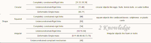
Table 2 summarizes our observations about robotic arm grippers handling items of various sizes, shapes, and materials. This table divides the gripper into three sizes based on the size of the handled object: small, medium, and giant. Furthermore, this chart takes into account the most frequent forms for classifying handling items, namely round, square, and irregular. The last comparison criterion takes into account the sorts of objects handled by the grippers, which include fragile, cloth, electronics, rocks and soils, and food. Because of their adaptability, deformable single-mass grippers are the best grippers for handling irregular items, according to the data shown in the table.
Table 2 summarizes the findings of actuation grippers for various item sizes, shapes, and materials.
However, the most commonly used gripper for everyday items is the under constrained-rigid link; this is because this form of gripper is easier to manufacture and requires a more readily accessible actuation system, such as linear or rotary actuators. Finally, Table 3 summarizes the key findings for each major gripper design area. This table summarizes the main characteristics of each gripper type, including weight capacity, range capacity, and the types of objects that each category can handle.
Table 3 shows the key findings for each major gripper design area.


My relatives always say that I am wasting my time here at web,
however I know I am getting experience all the time by
reading such nice content. https://www.waste-ndc.pro/community/profile/tressa79906983/
My brother suggested I might like this website. He was totally right.
This post actually made my day. You cann’t imagine simply how much time I
had spent for this info! Thanks! https://urs-wiscope.mystrikingly.com/
Thanks for finally writing about >Robotic Arm Gripper Designs – technoenvio.com <Liked it! https://caramellaapp.com/milanmu1/_zJdh2nHV/artemis-prostate-fusion-biopsy
Heya i am for the first time here. I came across this board and I find It truly useful & it
helped me out much. I hope to give something back and aid
others like you helped me. https://vidico.com/news/blockchain-animation/
Hello there, I found your web site by means of Google at the same time
as looking for a related subject, your website got here up, it
seems good. I have bookmarked it in my google bookmarks.
Hi there, simply was aware of your weblog via Google, and located that it’s truly informative.
I’m going to be careful for brussels. I will appreciate when you continue this in future.
A lot of folks can be benefited out of your writing. Cheers! https://menbehealth.wordpress.com/
Here to dive into discussions, share experiences, and gain fresh perspectives along the way.
I enjoy learning from different perspectives and sharing my input when it’s helpful. Always open to fresh thoughts and connecting with others.